
Related Manuals for REMKO RM Series


Summary of Contents for REMKO RM Series
- Page 1 REMKO RM RM 226, RM 235, RM 252, RM 268, RM 326, RM 335, RM 426, RM 435 Wall-mounted split design air conditioning unit Operation · Technology · Spare parts Edition GB – T05...
-
Page 3: Table Of Contents
Carefully read this operating manual prior to commissioning or using the equipment! This manual is an integral part of the unit and must be stored at the installation location or in the immediate vicinity. Made by REMKO Subject to modifications; No liability accepted for errors or misprints! -
Page 4: Safety Notes
REMKO as this may performing installation, repair or warranty" and commissioning cause malfunctions. maintenance work or cleaning report to REMKO GmbH & Co. KG the equipment. at the time when the equipment Equipment and components ■ was purchased and commissioned. -
Page 5: Transportation And Packaging
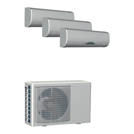
Compressor C equipment Connection valve Suction pipe C The RM 228-435 air conditioning Connection valve equipment consists of an REMKO Injection pipe C Compressor D RM...AT outdoor component and Connection valve two, three or four RM...IT interior Suction pipe D units. - Page 6 REMKO RM System layout Indoor area A Indoor area C Indoor unit C Indoor unit A Condensation pipe Condensation pipe Indoor area D Indoor area B Indoor unit D Indoor unit B Condensation pipe Condensation pipe Outdoor area Injection pipe...
-
Page 7: Operation
Operation The indoor unit is easy to operate using an infrared remote control. This is supplied as standard. The indoor unit beeps to acknowledge the correct transmission of data. If it is not possible to program the indoor unit using the remote control, it can also be manually operated. - Page 8 REMKO RM Buttons on the remote control 2. Cooling mode "TIMER OFF" Button In this mode the warm room Press this button to set an air is cooled to the desired automatic equipment switch-off temperature. time in the next 24 hours.
- Page 9 Button functions A symbol is shown on the display to indicate that the settings are being transferred. A flashing dot on the remote control indicates that the remote control is Remote control ready for operation ready for operation. RESET Button Pressing the RESET button in the battery compartment resets the remote control.
- Page 10 REMKO RM The▼ button is used to reduce the target temperature, the ▲ button ▲/▼ Buttons increases it. In automatic mode the temperature can be increased or decreased by 1°C. Temperature adjustment is not possible in dehumidifying mode. ▼ ▲...
- Page 11 In dehumidifying mode, the room temperature is reduced to 24°C. The DEHUMIDIFY Mode low refrigerant temperature causes the air temperature at the finned heat exchanger to fall below the dew point. Any excess humdity in the air condenses in the vaporiser. As a result the room is dehumidified. The fan speed should be set to automatic to achieve maximum dehumidification.
- Page 12 REMKO RM Press these buttons to activate a program which will raise the target SLEEP Buttons temperature in cooling mode by 1 °C and 2 °C after 1 and 2 hours respectively. The unit automatically switches off after 8 hours.
-
Page 13: Shutdown
2. Shut down the unit using the REMKO GmbH & Co. KG or their accidental switch-on! remote control. authorised partners will be pleased to provide details of specialists in 3. - Page 14 REMKO RM Maintenance Type of task It is recommended that you ■ take out a maintenance Checks/Maintenance/Inspection contract with an annual service from an appropriate specialist firm. • • General • • Measure voltage and current • • Check compressor/fans are functioning correctly This ensures the operational •...
-
Page 15: Troubleshooting And Customer Service
Troubleshooting and customer service The equipment and components are manufactured using state-of-the-art production methods and tested several times to verify their correct function. If malfunctions should occur, please check the functions as detailed in the list below. Please inform your dealer if the unit is still not working correctly after all the functional checks have been performed! Malfunction Fault... -
Page 16: Installation Instructions For Qualified Personnel
REMKO RM Error indicated by flashing code Display Cause Required action Faulty circulation sensor in indoor unit Contact specialist dealer Faulty frost protection sensor in indoor unit Contact specialist dealer Cooling mode: No cooling output after 30 min. Contact specialist dealer... - Page 17 Wall breakthroughs Selecting the installation Wind location The wall breakthrough must If the unit is being installed in ■ have a diameter of min. 70 mm Indoor unit windy areas, ensure that the and a fall of 10 mm from inside warm outlet air discharges in the to outside.
- Page 18 REMKO RM Installation inside buildings Ensure there is adequate heat Ensure a continuous and Comply with any regulations ■ ■ ■ dissipation when placing the unobstructed air flow from and conditions affecting outdoor component in cellars, outside, preferably using the statics of the building.
-
Page 19: Installation
Installation Oil return measures Connecting the refrigerant NOTE pipes Installation should only be If the outdoor component is performed by authorised installed at a higher level than The connections to the refrigerant specialists. the indoor unit, suitable oil return pipes are made at the rear of the measures must be taken. - Page 20 REMKO RM 5. Verify that the shape of the 10.Observe the permitted bending 12.Ensure that structure-borne flange is correct(Fig 9). radius for the refrigerant pipes sound is not transferred to parts during installation. Never bend of the building. Use vibration 6.
-
Page 21: Tightness Check
Condensation Tightness check Electrical connection connection Once all the connections have Units RM 226 to RM 335 require a If the temperature falls below the been established, the pressure single mains supply feed, whereas dew point, condensation will form units RM 426 to RM 435 require gauge station is attached as on the vaporiser during cooling. - Page 22 REMKO RM Mark the electrical control cable Connecting the indoor unit Connecting the outdoor ■ and associated refrigerant pipes component for each indoor unit with the Make the connection as follows: same letter (A to D). Proceed as follows to connect the Only connect up those cables/ 1.
-
Page 23: Electrical Connection Diagram
Electrical connection diagram RM 226 / RM 235 / RM 252 / RM 268 Outdoor Outdoor Indoor unit Indoor unit component component Circuit A Mains cable Circuit B Circuit A Circuit B Phase conductor Phase conductor Neutral conductor Neutral conductor 230 V, 1~, 50 Hz, Control conductor... -
Page 24: Electrical Circuit Diagram
REMKO RM Electrical circuit diagram RM 226 AT / RM 235 AT Liquefier fan Compressor A Compressor B Compressor Compressor contactor A contactor B contactor Colour code Brown Blue Black Orange Grey White To indoor unit A To indoor unit B... - Page 25 RM 268 AT Liquefier fan Liquefier fan Compressor A Compressor B Colour code Brown Blue Black Orange Grey White To indoor unit A To indoor unit B Green/yellow Mains cable RM 426 AT / RM 435 AT Compressor Compressor Compressor Compressor Liquefier fan Liquefier fan...
- Page 26 REMKO RM Electrical circuit diagram RM 326 AT / RM 335 AT Compressor Compressor Compressor contactor Colour code Brown Blue Black Orange Grey White To indoor unit A To indoor unit B To indoor unit C Green/yellow Mains cable RM 226 IT to RM 435 IT...
-
Page 27: Before Commissioning
Before commissioning After the tightness check has any interventions affecting the Perform this check when the been successfully completed, refrigerant circuit. Record the unit is not running . connect the vacuum pump via results in the commissioning the pressure gauge station to report: Check the refrigerant pipes and ■... -
Page 28: Commissioning
REMKO RM Commissioning Functional checks and Functional test for cooling mode NOTE test run Commissioning should only be 1. Remove the protective caps on performed and documented Check the following points. the valves. by specially trained personnel. Tightness of the refrigerant 2. -
Page 29: Unit Dimensions
9. Check the correct function 13.Check the overheating, Final tasks of the condensation pipe by outdoor, indoor, outlet and pouring distilled water into the vaporisation temperatures and Use the remote control to set ■ condensation tray. record the measured values in the target temperature to the A bottle with a spout is the commissioning report. - Page 30 REMKO RM Unit dimensions RM 226 AT / RM 235 AT RM 252 RM 268 RM 326 / RM 335 RM 426 RM 435 All values in mm We reserve the right to modify the dimensions and constructional design as part of the ongoing technical development process.
-
Page 31: Exploded View
Exploded view RM 226 IT to RM 435 IT We reserve the right to modify the dimensions and constructional design as part of the ongoing technical development process. Spare parts list RM 226 IT RM 326 IT 3,5 Designation RM 326 IT 2,6 RM 252 IT RM 268 IT RM 335 IT... - Page 32 REMKO RM Exploded view RM 226 AT to RM 268 AT We reserve the right to modify the dimensions and constructional design as part of the ongoing technical development process. Spare parts list Designation RM 226 AT RM 235 AT...
- Page 33 Exploded view RM 326 AT to RM 435 AT We reserve the right to modify the dimensions and constructional design as part of the ongoing technical development process. Spare parts list Designation RM 252 AT RM 268 AT RM 326 AT RM 335 AT RM 426 AT RM 435 AT Front panel 1109524 1109536...
-
Page 34: Technical Data
REMKO RM Technical data Series RM 226 RM 235 RM 252 RM 268 Operating mode Multisplit wall-mounted air-conditioning combinations for cooling Nominal cooling output 2 x 2.62 2 x 3.56 2 x 5.25 2 x 6.89 Energy efficiency class, cooling... - Page 35 Series RM 326 RM 335 RM 426 RM 435 Operating mode Multisplit wall-mounted air-conditioning combinations for cooling 2 x 2.62 Nominal cooling output 3 x 3.56 4 x 2.62 4 x 3.56 1 x 3.56 Energy efficiency class, cooling Energy efficiency ratio EER 2,95 3,02 3,02...
- Page 36 REMKO, a partner who helps solve problems. Sales REMKO not only has a well- established sales network at home and abroad, it also employs highly trained sales specialists. REMKOOur field staff are more...
Need help?
Do you have a question about the RM Series and is the answer not in the manual?
Questions and answers