
Related Manuals for Keysight Technologies 33210A


Summary of Contents for Keysight Technologies 33210A
- Page 1 Test Equipment Depot - 800.517.8431 - 99 Washington Street Melrose, MA 02176 - TestEquipmentDepot.com Keysight 33210A 10 MHz Function/Arbitrary Waveform Generator Service Guide...
-
Page 2: Safety Information
DOCUMENT IS PROVIDED “AS IS,” sition Regulation (“FAR”) 2.101. Pursu- AND IS SUBJECT TO BEING © Keysight Technologies 2008 - 2017 ant to FAR 12.212 and 27.405-3 and CHANGED, WITHOUT NOTICE, IN No part of this manual may be repro- Department of Defense FAR Supple- FUTURE EDITIONS. -
Page 3: Keysight 33210A At A Glance
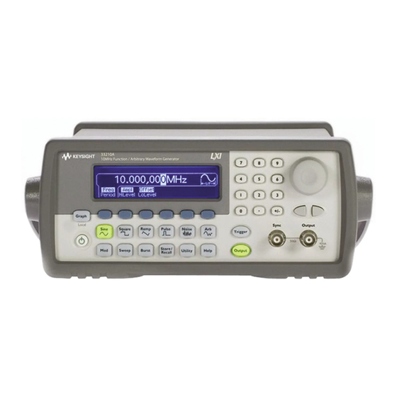
Keysight 33210A at a Glance The Keysight Technologies 33210A is a 10 MHz synthesized function generator with built-in arbitrary waveform and pulse capabilities. Its combination of bench-top and system features makes this function generator a versatile solution for your testing requirements now and in the future. -
Page 4: The Front Panel At A Glance
13 Sync Connector 6 Help Menu Key 14 Output Connector 7 Menu Operation Softkeys 8 Waveform Selection Keys To get context-sensitive help on any front-panel key or menu softkey, press and NOTE hold down that key. Keysight 33210A Service Guide... -
Page 5: The Front-Panel Display At A Glance
Readout Softkey Labels Graph Mode To enter or exit the Graph Mode, press the key. Parameter Parameter Name Value Signal Ground In Graph Mode, only one parameter label is displayed for each key at one time. Keysight 33210A Service Guide... -
Page 6: Front-Panel Number Entry
2 Rotate the knob to change a digit (clockwise to increase). Use the keypad to enter numbers and the softkeys to select units. 1 Key in a value as you would on a typical calculator. 2 Select a unit to enter the value. Keysight 33210A Service Guide... -
Page 7: The Rear Panel At A Glance
– Display the current network parameters (see Chapter The External and Internal 10 MHz Reference Terminals (1 and 2, above) are NOTE present only if Option 001, External Timebase Reference, is installed. Otherwise, the holes for these connectors are plugged. Keysight 33210A Service Guide... - Page 8 For protection from electrical shock, the power cord ground must not be WARNING defeated. If only a two-contact electrical outlet is available, connect the instrument’s chassis ground screw (see above) to a good earth ground. Keysight 33210A Service Guide...
-
Page 9: In This Book
Disassembly and Repair Chapter 6 provides guidelines for returning your function generator to Keysight Technologies for servicing, or for servicing it yourself. This chapter also contains a list of replaceable parts for the function generator and how to order the parts. -
Page 10: Waste Electrical And Electronic Equipment (Weee) Directive
The affixed product label is as shown below. Do not dispose in domestic household waste. Sales and Technical Support To contact Keysight for sales and technical support, refer to the support links on the following Keysight websites: Keysight 33210A Service Guide... -
Page 11: Table Of Contents
Table of Contents Keysight 33210A at a Glance ........3 The Front Panel at a Glance . - Page 12 ....69 Low Frequency Flatness Verification ......71 Keysight 33210A Service Guide...
- Page 13 Is the display working? ........113 Keysight 33210A Service Guide...
- Page 14 ........... 139 Keysight 33210A Service Guide...
-
Page 15: Specifications
Keysight 33210A 10 MHz Function/Arbitrary Waveform Generator Service Guide Specifications For the specifications and characteristics of the 33210A 10 MHz Function/ Arbitrary Waveform Generator, refer to the datasheet at http://literature.cdn.keysight.com/litweb/pdf/5989-8926EN.pdf... -
Page 16: 1 Specifications
Specifications THIS PAGE HAS BEEN INTENTIONALLY LEFT BLANK. Keysight 33210A Service Guide... - Page 17 Keysight 33210A 10 MHz Function/Arbitrary Waveform Generator Service Guide Quick Start Introduction To Prepare the Function Generator for Use To Adjust the Carrying Handle To Set the Output Frequency To Set the Output Amplitude To Set a DC Offset Voltage To Set the High-Level and Low-Level Values To Select “DC Volts”...
-
Page 18: Quick Start
To View a Waveform Graph on page 29 – To Output a Stored Arbitrary Waveform on page 30 – To Use the Built-In Help System on page 31 – To Rack Mount the Function Generator on page 33 Keysight 33210A Service Guide... -
Page 19: To Prepare The Function Generator For Use
– Keysight Automation-Ready CD (Keysight IO Libraries Suite). – USB 2.0 cable. All of the 33210A product documentation is provided on the Keysight 33210A NOTE Product Reference CD that comes with the product. 2 Connect the power cord and turn on the function generator. -
Page 20: To Adjust The Carrying Handle
Quick Start To Adjust the Carrying Handle To adjust the position, grasp the handle by the sides and pull outward. Then, rotate the handle to the desired position. Retracted Carrying Position Extended Keysight 33210A Service Guide... -
Page 21: To Set The Output Frequency
Press the softkey that corresponds to the desired units. When you select the units, the function generator outputs a waveform with the displayed frequency (if the output is enabled). For this example, press MHz. You can also enter the desired value using the knob and cursor keys. NOTE Keysight 33210A Service Guide... -
Page 22: To Set The Output Amplitude
Press the softkey that corresponds to the desired units. When you select the units, the function generator outputs the waveform with the displayed amplitude (if the output is enabled). For this example, press mV You can also enter the desired value using the knob and cursor keys. NOTE Keysight 33210A Service Guide... - Page 23 To change the displayed amplitude by decades, press the right-cursor key to move the cursor to the units on the right side of the display. Then, rotate the knob to increase or decrease the displayed amplitude by decades. Keysight 33210A Service Guide...
-
Page 24: To Set A Dc Offset Voltage
Press the softkey that corresponds to the desired units. When you select the units, the function generator outputs the waveform with the displayed offset (if the output is enabled). For this example, press mV You can also enter the desired value using the knob and cursor keys. NOTE Keysight 33210A Service Guide... -
Page 25: To Set The High-Level And Low-Level Values
Again, use the numeric keypad or the knob to enter a value of “0.0 V”. Note that these settings (high-level = “1.0 V” and low-level = “0.0 V”) are equivalent to setting an amplitude of “1.0 Vpp” and an offset of “500 mVdc”. Keysight 33210A Service Guide... -
Page 26: To Select "Dc Volts
DC On softkey. The Offset value becomes selected. 2 Enter the desired voltage level as an “Offset”. Enter 1.0 Vdc with the numeric keypad or knob. You can enter any dc voltage from -5 Vdc to +5 Vdc. Keysight 33210A Service Guide... -
Page 27: To Set The Duty Cycle Of A Square Wave
Using the numeric keypad or the knob, select a duty cycle value of “30”. The function generator adjusts the duty cycle immediately and outputs a square wave with the specified value (if the output is enabled). Keysight 33210A Service Guide... -
Page 28: To Configure A Pulse Waveform
Press the Edge Time softkey and then set the edge time for both the rising and falling edges to 50 ns. The edge time represents the time from the 10% threshold to the 90% threshold of each edge (note the display icon). Keysight 33210A Service Guide... -
Page 29: To View A Waveform Graph
Graph Mode. However, you can see only one label for each softkey at one time (for example, Freq or Period). – To exit the Graph Mode, press again. key also serves as a key to restore front-panel control after NOTE remote interface operations. Keysight 33210A Service Guide... -
Page 30: To Output A Stored Arbitrary Waveform
Quick Start To Output a Stored Arbitrary Waveform Arbitrary waveforms are optionally available with the 33210A (Option 002). NOTE There are five built-in arbitrary waveforms stored in non-volatile memory. The following steps show you how to output the built-in “exponential fall” waveform from the front panel. -
Page 31: To Use The Built-In Help System
Press and hold down the Freq softkey. If the message contains more information than will fit on the display, press the ↓ softkey or rotate the knob clockwise to view the remaining information. Press DONE to exit Help. Keysight 33210A Service Guide... - Page 32 The menu softkey labels and status line messages are not translated. To select the local language, press the key, press the System softkey, and then press the Help In softkey. Select the desired language. Keysight 33210A Service Guide...
-
Page 33: To Rack Mount The Function Generator
Quick Start To Rack Mount the Function Generator You can mount the Keysight 33210A in a standard 19-inch rack cabinet using one of two optional kits available. Instructions and mounting hardware are included with each rack-mounting kit. Any Keysight System II instrument of the same size can be rack-mounted beside the Keysight 33210A. - Page 34 In order to prevent overheating, do not block the flow of air into or out of the NOTE instrument. Be sure to allow enough clearance at the rear, sides, and bottom of the instrument to permit adequate internal air flow. Keysight 33210A Service Guide...
- Page 35 Keysight 33210A 10 MHz Function/Arbitrary Waveform Generator Service Guide Front-Panel Menu Operation Introduction Front-Panel Menu Reference To Select the Output Termination To Reset the Function Generator To Read the Calibration Information To Unsecure and Secure for Calibration To Store the Instrument State...
-
Page 36: Front-Panel Menu Operation
It does, however, give you an overview of the front-panel menus and many front-panel operations. Refer to the Keysight 33210A User’s Guide for a complete discussion of the function generator’s capabilities and operation. -
Page 37: Front-Panel Menu Reference
– Specify an internal or external trigger source for the sweep. – Specify the slope (rising or falling edge) for an external trigger source. – Specify the slope (rising or falling edge) of the “Trig Out” signal. Keysight 33210A Service Guide... - Page 38 – Store up to four instrument states in non-volatile memory. – Assign a custom name to each storage location. – Recall stored instrument states. – Restore all instrument settings to their factory default values. – Select the instrument’s power-on configuration (last or factory default). Keysight 33210A Service Guide...
- Page 39 – Enable / disable the display bulb-saver mode. – Adjust the contrast setting of the front-panel display. – Perform an instrument self-test. – Secure/unsecure the instrument for calibration and perform manual calibrations. – Query the instrument’s firmware revision codes. Keysight 33210A Service Guide...
- Page 40 – How to create an arbitrary waveform. – How to reset the instrument to its default state. – How to view a waveform in the Graph Mode. – How to synchronize multiple instruments. – How to obtain Keysight Technical Support. Keysight 33210A Service Guide...
-
Page 41: To Select The Output Termination
Front-Panel Menu Operation To Select the Output Termination The Keysight 33210A has a fixed series output impedance of 50 ohms to the front-panel Output connector. If the actual load impedance is different than the value specified, the displayed amplitude and offset levels will be incorrect. The load impedance setting is simply provided as a convenience to ensure that the displayed voltage matches the expected load. -
Page 42: To Reset The Function Generator
To reset the instrument to its factory default state, press and then select the Set to Defaults softkey. Press YES to confirm the operation. For a complete listing of the instrument’s power-on and reset conditions, see “Keysight 33210A Factory Default Settings” in the User’s Guide. Keysight 33210A Service Guide... -
Page 43: To Read The Calibration Information
The last line indicates the current version of the firmware. The calibration information will time-out and disappear after a few seconds. Select the Cal Info softkey to show the information again. 2 Exit the menu. Press the DONE softkey. Keysight 33210A Service Guide... -
Page 44: To Unsecure And Secure For Calibration
12 characters but the first character must always be a letter. If you forget your security code, you can disable the security feature by applying NOTE a temporary short inside the instrument as described in “To Unsecure the Instrument Without the Security Code” on page 78. Keysight 33210A Service Guide... -
Page 45: To Unsecure For Calibration
Use the knob to change the displayed character. Use the arrow keys to move to the next character When the last character of the secure code is entered, the instrument will be unsecured. 3 Exit the menu. Press the DONE softkey. Keysight 33210A Service Guide... -
Page 46: To Secure After Calibration
Use the knob to change the displayed character. Use the arrow keys to move to the next character 3 Secure the Instrument. Select the Secure softkey. 4 Exit the menu. Press the DONE softkey. Keysight 33210A Service Guide... -
Page 47: To Store The Instrument State
Press the STORE STATE softkey. The instrument stores the selected function, frequency, amplitude, dc offset, duty cycle, symmetry, as well as any modulation parameters in use. The instrument does not store volatile waveforms created in the arbitrary waveform function. Keysight 33210A Service Guide... -
Page 48: To Configure The Remote Interface
The USB interface requires no front panel configuration parameters. Just connect the Keysight 33210A to your PC with the appropriate USB cable. The interface will self configure. Press the Show USB Id softkey in the “I/O menu” to see the USB interface identification string. -
Page 49: Lan Configuration
From this menu, you can select Reset LAN to restart the LAN, IP Setup to set an IP address and related parameters, DNS Setup to configure DNS, or Password to set a password for the Web Server Interface. Keysight 33210A Service Guide... - Page 50 “Keysight 33210A Web Interface” of the User’s Guide for the Keysight 33210A. 3 Establish an “IP Setup.” To use the Keysight 33210A on the network, you must first establish an IP setup, including an IP address, and possibly a subnet mask and gateway address.
- Page 51 Press the Default Gateway softkey and enter the gateway address in the IP address format (using the keypad). d Exit the “IP Setup” menu. Press DONE to return to the "Modify Settings" menu. Keysight 33210A Service Guide...
- Page 52 Set the “DNS Server” address. Press the DNS Server softkey and enter the address of the DNS server in the IP address format (using the keypad). Keysight 33210A Service Guide...
- Page 53 ".011" as "9". To avoid confusion it is best to use only decimal expressions of byte values (0 to 255), with no leading zeros. The Keysight 33210A assumes that all IP addresses and other dot-notation addresses are expressed as decimal byte values, and strips all leading zeros from these byte values.
- Page 54 Front-Panel Menu Operation THIS PAGE HAS BEEN INTENTIONALLY LEFT BLANK. Keysight 33210A Service Guide...
-
Page 55: Calibration Procedures
Keysight 33210A 10 MHz Function/Arbitrary Waveform Generator Service Guide Calibration Procedures Introduction Keysight Technologies Calibration Services Calibration Interval Adjustment is Recommended Time Required for Calibration Automating Calibration Procedures Recommended Test Equipment Test Considerations Performance Verification Tests Internal Timebase Verification AC Amplitude (high-impedance) Verification... - Page 56 Frequency (Internal Timebase) Adjustment Internal ADC Adjustment/Self Calibration Output Impedance Adjustment AC Amplitude (high-impedance) Adjustment Low Frequency Flatness Adjustment 0 dB Range Flatness Adjustments +10 dB Range Flatness Adjustments +20 dB Range Flatness Adjustment Calibration Errors Keysight 33210A Service Guide...
-
Page 57: Introduction
83 – Sequence of Adjustments on page 84 – Self-Test on page 85 – Frequency (Internal Timebase) Adjustment on page 86 – Internal ADC Adjustment/Self Calibration on page 88 – Output Impedance Adjustment on page 90 Keysight 33210A Service Guide... -
Page 58: Keysight Technologies Calibration Services
Keysight Technologies Calibration Services Keysight Technologies offers calibration services at competitive prices. When your instrument is due for calibration, contact your local Keysight Service Center for recalibration. -
Page 59: Adjustment Is Recommended
Performance data measured during Performance Verification Tests does not mean that the instrument will remain within these limits unless the adjustments are performed. Use the "Calibration Count" feature (see page 81) to verify that all adjustments have been performed. Keysight 33210A Service Guide... -
Page 60: Time Required For Calibration
Calibration Procedures Time Required for Calibration The Keysight 33210A can be automatically calibrated under computer control. With computer control you can perform the complete calibration procedure and performance verification tests in approximately 30 minutes once the instrument is warmed-up (see Test Considerations on page 63). -
Page 61: Automating Calibration Procedures
The instrument must be unsecured prior to initiating the calibration procedure. For further information on programming the instrument, see Chapters 3 and 4 in the Keysight 33210A User’s Guide. Keysight 33210A Service Guide... -
Page 62: Recommended Test Equipment
Q, P, T Cable RG58, BNC (m) to BNC (m) Keysight 8120-1840 Q, P, T [a] Q = Quick Verification P = Performance Verification T = Troubleshooting [b] An oscilloscope is not required for calibration, only for troubleshooting. Keysight 33210A Service Guide... -
Page 63: Test Considerations
– Assure ambient relative humidity is less than 80%. – Allow a 1-hour warm-up period before verification or adjustment. – Keep the measurement cables as short as possible, consistent with the impedance requirements. – Use only RG-58 or equivalent 50 cable. Ω Keysight 33210A Service Guide... -
Page 64: Performance Verification Tests
– If the self-test is successful, “Self Test Passed” is displayed on the front panel. – If the self-test fails, “Self Test Failed” and an error number are displayed. – If repair is required, see Chapter 6, "Disassembly and Repair", for further details. Keysight 33210A Service Guide... -
Page 65: Quick Performance Check
(beginning on page 71). Additional reference measurements and calculated references are used in the flatness verification procedures. Photo-copy and use the table on page 67 to record these reference measurements and perform the calculations. Keysight 33210A Service Guide... - Page 66 Power (dBm) = 10 log(5.0 * V Flatness measurements for the –10 db, –20d B, and –30 dB attenuator ranges are verified as a part of the 0 dB verification procedure. No separate verification procedure is given for these ranges. Keysight 33210A Service Guide...
- Page 67 __________________________ dBm 5 Calculate the offset values. 100kHz_0dB_reference_dBm – 1kHz_0dB_reference_dBm 100kHz_0dB_offset __________________________ dBm (use on page 72) – 100kHz_10dB_reference_dBm 1kHz_10dB_reference_dBm 100kHz_10dB_offset __________________________ dBm (use on page 74) 100kHz_20dB_reference_dBm – 1kHz_20dB_reference_dBm 100kHz_20dB_offset __________________________ dBm (use on page 76) Keysight 33210A Service Guide...
-
Page 68: Internal Timebase Verification
10.000 MHz ± 200 Hz [a] The error is ± 100 Hz within 90 days of calibration, or ± 200 Hz within one year. 3 Compare the measured frequency to the test limits shown in the table. Keysight 33210A Service Guide... -
Page 69: Ac Amplitude (High-Impedance) Verification
[a] Based upon 1% of setting ±1 mVpp (50 W); converted to Vrms for High–Z. [b] Enter the measured value on the worksheet (76) as 1kHz_0dB_reference. [c] Enter the measured value on the worksheet (76) as 1kHz_10dB_reference. Keysight 33210A Service Guide... - Page 70 Calibration Procedures [d] Enter the measured value on the worksheet (76) as 1kHz_20dB_reference. 3 Compare the measured voltage to the test limits shown in the table. Keysight 33210A Service Guide...
-
Page 71: Low Frequency Flatness Verification
3 Compare the measured voltage to the test limits shown in the table. 4 You have now recorded all the required measurements on the worksheet (page 67). Complete the worksheet by making all the indicated calculations. Keysight 33210A Service Guide... -
Page 72: Db Range Flatness Verification
4 Set the power meter offset to equal the 100kHz_0dB_offset value previously calculated. This sets the power meter to directly read the flatness error specification relative to 1 kHz. 100kHz_0dB_offset is calculated on the "Amplitude and Flatness Verification Worksheet". Keysight 33210A Service Guide... - Page 73 Sine Wave +3.51 dBm 8.000 MHz 0 dB ± 0.3 dB 50 Ω Sine Wave +3.51 dBm 10.000 MHz 0 dB ± 0.3 dB 6 Compare the measured output to the test limits shown in the table. Keysight 33210A Service Guide...
-
Page 74: Db Range Flatness Verification
Sine Wave +13.00 dBm 3.000 MHz 0 dB ± 0.2 dB 50 Ω Sine Wave +13.00 dBm 4.000 MHz 0 dB ± 0.2 dB 50 Ω Sine Wave +13.00 dBm 5.000 MHz 0 dB ± 0.2 dB Keysight 33210A Service Guide... - Page 75 Sine Wave +13.00 dBm 8.000 MHz 0 dB ± 0.3 dB 50 Ω Sine Wave +13.00 dBm 10.000 MHz 0 dB ± 0.3 dB 6 Compare the measured output to the test limits shown in the table. Keysight 33210A Service Guide...
-
Page 76: +20 Db Range Flatness Verification
+20 dB output. 2 Set up the function generator as follows: – Output impedance: 50 Ω (press and select Output Setup). – Waveform: Sine – Frequency: 100 kHz – Amplitude: 23.90 dBm Make sure the output is enabled. Keysight 33210A Service Guide... - Page 77 Sine Wave +23.90 dBm 8.000 MHz 0 dB ± 0.3 dB 50 Ω Sine Wave +23.90 dBm 10.000 MHz 0 dB ± 0.3 dB 6 Compare the measured output to the test limits shown in the table. Keysight 33210A Service Guide...
-
Page 78: Calibration Security
If that code does not work, you may wish to try the single letter A as the security code. If someone has re-secured calibration without entering a new code, the default code is the letter A. 1 Disconnect the power cord and all input connections. Keysight 33210A Service Guide... - Page 79 6 Turn off the instrument and remove the power cord. 7 Reassemble the instrument. Now you can enter a new security code, see “To Unsecure and Secure for Calibration” on page 44. Be sure you record the new security code. Keysight 33210A Service Guide...
-
Page 80: Calibration Message
You can read the calibration message whether the instrument is secured or unsecured. Reading the calibration message from the front panel is described “To Read the Calibration Information” on page 43. Use the CAL:STRING? query to read the message over the remote interface. Keysight 33210A Service Guide... -
Page 81: Calibration Count
The count value increments by one for each calibration point, and a complete calibration may increase the value by many counts. See “To Read the Calibration Information” on page 43. Use the CAL:COUNT? query to read the count over the remote interface. Keysight 33210A Service Guide... -
Page 82: General Calibration/Adjustment Procedure
To cancel the adjustment procedure, select CANCEL STEP. The display will NOTE return to the setup number entry. 11 When finished, select END CAL. 12 Secure the instrument against calibration. 13 Note the new security code and calibration count in the instrument’s maintenance records. Keysight 33210A Service Guide... -
Page 83: Aborting A Calibration In Progress
If power is lost when the instrument is attempting to write new calibration CAUTION constants to EEPROM, you may lose all calibration constants for the function. Typically, upon re-applying power, the instrument will report error “-313, Calibration Memory Lost”. Keysight 33210A Service Guide... -
Page 84: Sequence Of Adjustments
You may perform individual adjustments as necessary. Setups 1 through 7 must be performed in order and must be performed before any other setup procedure. Keysight 33210A Service Guide... -
Page 85: Self-Test
Performs the Self-test. The Main Output is disabled during test. 2 If the instrument fails any self-test, you must repair the instrument before continuing the adjustment procedures. The self-test procedure takes approximately 15 seconds to complete. NOTE Keysight 33210A Service Guide... -
Page 86: Frequency (Internal Timebase) Adjustment
Output frequency should be 10MHz ±1ppm [a] Constants are stored after completing this setup. 3 Using the numerical keypad or knob, adjust the displayed frequency at each setup to match the measured frequency. Select ENTER VALUE. 4 After performing setup 5: Keysight 33210A Service Guide... - Page 87 If your calibration procedures require you to verify the adjustment just made, exit the calibration menu and perform “Internal Timebase Verification” on page 68. b If you are making all the adjustments and then verifying the instrument’s performance, continue with the next procedure in this chapter. Keysight 33210A Service Guide...
-
Page 88: Internal Adc Adjustment/Self Calibration
[a] Constants are stored after completing this setup. 4 Enter the measured value of the dc source using the numeric keypad or knob. This setup requires approximately 15 seconds to complete. NOTE 5 Disconnect all cables from the rear panel Modulation In connector. Keysight 33210A Service Guide... - Page 89 [a] Constants are stored after completing this setup. 7 There are no specific operational verification tests for setups 6 and 7 since the constants generated affect almost all behavior of the instrument. Continue with the next adjustment procedure in this chapter. Keysight 33210A Service Guide...
-
Page 90: Output Impedance Adjustment
2 Use the DMM to make a resistance measurement at the front panel Output connector for each setup in the following table. The expected measured value is approximately 50 Ω. Setup -30dB range -20dB range -10dB range Keysight 33210A Service Guide... - Page 91 3 Using the numeric keypad or knob, adjust the displayed impedance at each setup to match the measured impedance. Select ENTER VALUE. 4 There are no specific operational verification tests for Output Impedance. Continue with the next adjustment procedure in this chapter. Keysight 33210A Service Guide...
-
Page 92: Ac Amplitude (High-Impedance) Adjustment
-0.015 V Output of -30dB range +0.05 V Output of -20dB range -0.05 V Output of -20dB range +0.15 V Output of -10dB range -0.15 V Output of -10dB range +0.50 V Output of 0dB range Keysight 33210A Service Guide... - Page 93 “AC Amplitude (high-impedance) Verification” on page 69. b If you are making all the adjustments and then verifying the instrument’s performance, continue with the next procedure in this chapter. Keysight 33210A Service Guide...
-
Page 94: Low Frequency Flatness Adjustment
Select ENTER VALUE. 4 After performing setup 38: a If your calibration procedures require you to verify the adjustment just made, exit the calibration menu and perform “Low Frequency Flatness Verification” on page 71. Keysight 33210A Service Guide... - Page 95 Calibration Procedures b If you are making all the adjustments and then verifying the instrument’s performance, continue with the next procedure in this chapter. Keysight 33210A Service Guide...
-
Page 96: Db Range Flatness Adjustments
Flatness for 0 dB, Linear Phase Filter 3.0 MHz 0.28 Vrms 2 dBm Flatness for 0 dB, Linear Phase Filter Setup not used for this instrument Setup not used for this instrument [a] Constants are stored after completing this setup. Keysight 33210A Service Guide... - Page 97 “0 dB Range Flatness Verification” on page 72. b If you are making all the adjustments and then verifying the instrument’s performance, continue with the next procedure in this chapter. Keysight 33210A Service Guide...
-
Page 98: +10 Db Range Flatness Adjustments
You must always perform setup 54 before any of the following setups. Nominal Signal Setup Frequency Amplitude 100 kHz 0.9 Vrms 12 dBm Flatness for 10 dB, Elliptical Filter 200 kHz 0.9 Vrms 12 dBm Flatness for 10 dB, Elliptical Filter Keysight 33210A Service Guide... - Page 99 “+10 dB Range Flatness Verification” on page 74. b If you are making all the adjustments and then verifying the instrument’s performance, continue with the next procedure in this chapter. Keysight 33210A Service Guide...
-
Page 100: +20 Db Range Flatness Adjustment
2 Use the power meter to measure the output amplitude for each of the setups in the table on the next page. Setup 63 establishes the power meter reference for all the remaining setups in NOTE this table. You must always perform setup 63 before any of the following setups. Keysight 33210A Service Guide... - Page 101 (in dBm). Then select ENTER VALUE. In order to get dBm you must use the numeric keypad (not the knob) to enter the NOTE number, and then select “dBm”. 4 After performing setup 75: Keysight 33210A Service Guide...
- Page 102 If you are making all the adjustments and then verifying the instrument’s performance, verify the output specifications of the instrument using the “Performance Verification Tests” on page 64. You have now completed the recommended adjustment procedures. Verification of the output specifications is recommended. Keysight 33210A Service Guide...
-
Page 103: Calibration Errors
Calibration Errors The following errors are failures that may occur during a calibration. System error messages are described in the Keysight 33210A User’s Guide. Self-test error messages are described on page 120 of this document 701: Calibration error; security defeated by hardware jumper The function generator’s calibration security feature has been disabled by... - Page 104 You have selected an invalid calibration setup number with the CAL:SET command. 851: Calibration error; set up is out of order Certain calibration steps require a specific beginning and ending sequence. You may not enter into the middle of a sequence of calibration steps. Keysight 33210A Service Guide...
-
Page 105: Introduction Block Diagram Power Supplies
Keysight 33210A 10 MHz Function/Arbitrary Waveform Generator Service Guide Block Diagram Introduction Block Diagram Power Supplies... -
Page 106: Block Diagram Introduction
This chapter provides a high-level overview of the instrument's functional block diagram. For more information on servicing the instrument, see Chapter 6, "Disassembly and Repair". – Block Diagram on page 107 – Power Supplies on page 110 Keysight 33210A Service Guide... - Page 107 (x)/x correction. This filter is used for continuous sine and squarewaves. – A 7 order linear phase filter with a cutoff frequency of 12.5 MHz. This filter is used for ramp, noise, and arbitrary waveforms. Keysight 33210A Service Guide...
- Page 108 –10 dB –20 dB –10 dB –20dB 10 V to 3.16 V 3.16 V to 1 V 1 V to 0.316 V 0.316 V to 0.1 V 0.1 V to 0.0316 V 0.0316 to 0.01 V Keysight 33210A Service Guide...
- Page 109 The output is protected by a relay. When the relay is open, the instrument can read the value of the Main Output Circuit. The output relay is opened on user command, if a current overload is detected, or if a voltage over–range condition is found. Keysight 33210A Service Guide...
- Page 110 +15V +12V Isolated Line Power +3.3V_ISO 110-240 Vac Main Supply PWR_ON Filter Supplies +1.8V_ISO –5V –15V K1201 +3.3V_ER Power Earth +1.8V_ER Switch Referenced Power Supplies Display Backlight CCFL_ON Front Panel A1 Power Supplies (from U101) Keysight 33210A Service Guide...
-
Page 111: Disassembly And Repair
Keysight 33210A 10 MHz Function/Arbitrary Waveform Generator Service Guide Disassembly and Repair Service Operating Checklist Types of Service Available Repackaging for Shipment Cleaning Electrostatic Discharge (ESD) Precautions Surface Mount Repair Troubleshooting Hints Self-Test Procedures Mechanical Disassembly Replaceable Parts... -
Page 112: Service
Disassembly and Repair Service This chapter discusses the procedures involved for returning a failed instrument to Keysight Technologies for service or repair. Subjects covered include the following: – Operating Checklist on page 113 – Types of Service Available on page 114 –... -
Page 113: Operating Checklist
Disassembly and Repair Operating Checklist Before returning your instrument to Keysight Technologies for service or repair, check the following items: Is the instrument inoperative? – Verify that the ac power cord is connected to the instrument. – Verify that the front-panel On/Standby switch has been pushed. -
Page 114: Types Of Service Available
Disassembly and Repair Types of Service Available If your instrument fails during the warranty period, Keysight Technologies will repair or replace it under the terms of your warranty. After your warranty expires, Keysight offers repair services at competitive prices. Extended Service Contracts Many Keysight products are available with optional service contracts that extend the covered period after the standard warranty expires. -
Page 115: Repackaging For Shipment
Keysight suggests that you always insure shipments. Cleaning Clean the outside of the instrument with a soft, lint-free, slightly dampened cloth. Do not use detergent. Disassembly is not required or recommended for cleaning. Keysight 33210A Service Guide... -
Page 116: Electrostatic Discharge (Esd) Precautions
Surface mount components should only be removed using soldering irons or desoldering stations expressly designed for surface mount components. Use of conventional solder removal equipment will almost always result in permanent damage to the printed circuit board and will void your Keysight Technologies factory warranty. Keysight 33210A Service Guide... -
Page 117: Troubleshooting Hints
Use the menu to set the display contrast. Unit Fails Self-Test Ensure that all terminal connections (both front panel and rear terminals) are removed while the self-test is performed. Keysight 33210A Service Guide... -
Page 118: Power Supply
Replace the entire main power suppl y assembl y if the input fuse fails. Note that a power supply failure may be caused by a failure elsewhere in the instrument. Keysight 33210A Service Guide... -
Page 119: Self-Test Procedures
The self-test will complete in approximately 30 seconds. – If the self-test is successful, “Self Test Pass” is displayed on the front panel. – If the self-test fails, “Self Test Fail” and an error number are displayed. Keysight 33210A Service Guide... -
Page 120: Self-Tests
622: Self-test failed; time base calibration DAC This error indicates that the time base calibration DAC in the synthesis IC, or voltage controlled oscillator has failed. 626: Self-test failed; waveform filter path select relay 627: Self-test failed; -10 dB attenuator path Keysight 33210A Service Guide... - Page 121 This error indicates a probable ADC failure. The failure could be of the system ADC, the ADC input multiplexer, or the ADC input buffer amplifier. 632: Self-test failed; square/pulse DAC test failure This error indicates a probable failure of the square/pulse DAC. Keysight 33210A Service Guide...
-
Page 122: Mechanical Disassembly
To avoid electrical shock and personal injury, make sure to disconnect the power cord from the instrument before removing the covers. Some circuits are active and have power applied even when the power switch is turned off. Keysight 33210A Service Guide... -
Page 123: General Disassembly Procedure
Disassembly and Repair General Disassembly Procedure 1 Turn off the power. Remove all cables from the instrument. 2 Rotate the handle upright and pull off. 3 Pull off the instrument bumpers. Keysight 33210A Service Guide... - Page 124 Disassembly and Repair 4 Loosen the two captive screws in the rear bezel and remove the rear bezel. Loosen Screws 5 Slide off the instrument cover. Slide Cover Off Keysight 33210A Service Guide...
- Page 125 6 Remove the two screws securing the power supply deck to the chassis. Lift off the deck. The power supply assembly is attached to the deck. 7 Lay the deck and power supply assembly to the side. Keysight 33210A Service Guide...
- Page 126 SHOCK HAZARD. Only service-trained personnel who are aware of the WARNING hazards involved should remove the instrument covers. Dangerous voltages may be encountered with the instrument covers removed. Keysight 33210A Service Guide...
-
Page 127: Removing The Main Power Supply Assembly
Disconnect the line input, ground, and output cables from the power supply. The main power supply should be replaced as an assembly. Always be sure to re-attach the green ground wire to the power supply WARNING before operating the instrument. Captive screw Keysight 33210A Service Guide... -
Page 128: Front-Panel Removal Procedure
PC board (A1 assembly). To prevent damage to the cable and connector, use care when lifting the CAUTION actuator. Excessive or uneven force may damage the actuator or connector. Flat Flex Cable Keysight 33210A Service Guide... - Page 129 Disassembly and Repair 2 Remove the two screws from the front edge of the main PC board (A1 assembly). Keysight 33210A Service Guide...
- Page 130 3 Push the side flanges of the chassis inward while lifting off the front panel. There should now be enough play in the chassis sides and front panel assembly to allow the side of the front panel to be disconnected from the chassis. Keysight 33210A Service Guide...
-
Page 131: Front-Panel Disassembly
Disassembly and Repair Front-Panel Disassembly 1 Loosen the captive screw holding the support plate. Lift the end of the support plate and rotate out of the front panel assembly. Captive Screw Keysight 33210A Service Guide... - Page 132 PC board. Lift out the display assembly. To prevent damage to the cable and connector, use care when lifting the CAUTION actuator. Excessive or uneven force may damage the actuator or connector. Inverter Cable Flat Flex Cable Keysight 33210A Service Guide...
- Page 133 Disassembly and Repair 3 Pull to remove the knob. Lift out the keyboard PC board (A2 assembly). Keysight 33210A Service Guide...
-
Page 134: External Timebase Circuit Board Disassembly
10 MHz Out BNC connectors. Pull the External Timebase PC board (A3 assembly) from the back panel as shown below. Then unplug the captive ribbon cable from the keyed connector on the main PC board (J601 on the A1 assembly). Remove the A3 assembly from the chassis. Keysight 33210A Service Guide... -
Page 135: Replaceable Parts
Rotary Encoder 1250-2913 MOD IN BNC 1250-3569 Output/Sync BNC 1252-2161 GPIB Connector 1253-5030 LAN Connector 2090-0886 Display 33210-60201 Front Panel 33210-80001 Opt 001 Retrofit Kit 33220-66502 Front Panel PCB 33220-67601 Assembly Line Filter 33220-68501 Fan Assembly Keysight 33210A Service Guide... - Page 136 Disassembly and Repair Keysight Part Number Description 33220-84101 Cover 33220-87910 Power Supply Assembly 33220-88304 Rear Bezel 33250-49301 Window 33250-87401 Knob 34401-45021 Handle 34401-86020 Bumper Kit Keysight 33210A Service Guide...
-
Page 137: Backdating
Keysight 33210A 10 MHz Function/Arbitrary Waveform Generator Service Guide Backdating This chapter normally contains information necessary to adapt this manual to instruments not directly covered by the current content. At this printing, the manual applies to all instruments. - Page 138 Backdating THIS PAGE HAS BEEN INTENTIONALLY LEFT BLANK. Keysight 33210A Service Guide...
-
Page 139: Index
DC volts high Z load front-panel selection setting output amplitude DHCP front-panel selection display output frequency overview IEEE-488 front-panel selection display, graph mode connector output period dot notation Keysight 33210A Service Guide... - Page 140 Keysight 33210A Service Guide...
- Page 141 This information is subject to change without notice. Always refer to the Keysight website for the latest revision. © Keysight Technologies 2008 - 2017 Edition 2, October 1, 2017 Printed in Malaysia *33210-90010*...
Need help?
Do you have a question about the 33210A and is the answer not in the manual?
Questions and answers