Table of Contents
Advertisement
Quick Links
Advertisement
Table of Contents

Related Manuals for Keysight Technologies AP5001A


Summary of Contents for Keysight Technologies AP5001A
- Page 1 Keysight AP5001A, AP5002A Analog Signal Generator USER’S MANUAL...
-
Page 2: Safety Notices
DOCUMENT THAT CONFLICT WITH apply, except to the extent that THESE TERMS, THE WARRANTY those terms, rights, or licenses are © Keysight Technologies, Inc. 2024 TERMS IN THE SEPARATE explicitly required from all No part of this manual may be AGREEMENT WILL CONTROL. -
Page 3: Where To Find The Latest Information
Where to Find the Latest Information Documentation is updated periodically. For the latest information about these products, including instrument software upgrades, application information, and product information, browse to one of the following URLs, according to the name of your product: https://www.keysight.com/us/en/products/signal-generators-signal-sources/compact-signal-generators. - Page 4 Product and Solution Cybersecurity Keysight complies with multinational regulations for the cybersecurity of its own products and is committed to providing information to assist you in protecting your products and solutions from external cyber threats. For more information, see: https://www.keysight.com/us/en/about/quality-and-security/security/product-and-solution-cyber-security.html Keysight also recommends that you secure your IT environments using appropriate third-party tools.
-
Page 5: Table Of Contents
Contents Contents 1 Quick Start Introduction Models Covered in this Manual Available Casing Data Connections Signal Connections Transportation Safety Information Safety Symbols Instrument Markings General Safety Considerations Technical Specifications Minimum Distances Energizing and de-Energizing Protective Earth Proper Operating Conditions Environmental Information Getting Started Included Material System Requirements... - Page 6 Contents CONTROL Menu CW Menu SWEEP Menu MODULATION Menu REFERENCE Menu TRIGGER Menu LF OUT Menu Simultaneously Controlling Multiple Signal Generators from one PC Store and Load Instrument States Setting Network Configuration Multi-Session Option Device Port Setting Connecting two devices using a non-default port and non-default network interface Firmware Upgrade Multi-Output GUI Control...
- Page 7 Contents Cleaning Repair Warranty Information...
- Page 8 Contents...
-
Page 9: Quick Start
Keysight AP5001A/AP5002A Signal Generator User’s Manual Quick Start The following topics can be found in this section: “Introduction” on page 10 “Safety Information” on page 12 “Technical Specifications” on page 16 “Getting Started” on page 19... -
Page 10: Introduction
The devices may only be connected to a network or a computer by using a shielded LAN cable. Unless shorter lengths are prescribed, a maximum length of 3 m must not be exceeded for the LAN and the USB connection. Keysight AP5001A/AP5002A Signal Generator User’s Manual... -
Page 11: Signal Connections
20 GHz. Transportation The devices must only be transported with the packaging supplied by the manufacturer. The device can be lifted up or transported in any orientation. Keysight AP5001A/AP5002A Signal Generator User’s Manual... -
Page 12: Safety Information
This symbol marks the ON position of the power line switch. This symbol marks the OFF position of the power line switch. This symbol indicates that the input power required is AC. This symbol indicates DC voltage Keysight AP5001A/AP5002A Signal Generator User’s Manual... - Page 13 The Keysight email address is required by EU directives applicable to our product. The CSA mark is a registered trademark of the CSA International. Canada EMC label. Interference-Causing Equipment Standard for industrial, scientific and medical (ISM) equipment. Matériel industriel, scientifique et médical (ISM). Keysight AP5001A/AP5002A Signal Generator User’s Manual...
- Page 14 GB 18455-2001 as required by the China RoHS regulations for paper/fiberboard packaging. This mark indicates product has been designed to meet the requirements of "IP x y", where "x" is the solid particle protection and "y" is the liquid ingress protection. Keysight AP5001A/AP5002A Signal Generator User’s Manual...
-
Page 15: General Safety Considerations
(heavy-metal dust such as nickel) may be released. For this reason, the product may only be disassembled or opened by specially trained personnel. Improper disassembly may be hazardous to your health. National waste disposal regulations must be observed. Keysight AP5001A/AP5002A Signal Generator User’s Manual... -
Page 16: Technical Specifications
If the instrument is energized, it needs to be positioned where it is easy to de-energize. There should always be enough space to allow easy and fast separation of the instrument from the power connector or to turn off the AC power switch. Keysight AP5001A/AP5002A Signal Generator User’s Manual... -
Page 17: Protective Earth
Figure 1-3 Position of the power connector on the right. Protective Earth It is prohibited to use the AP5001A or AP5002A without adequate protective earth connection. Before powering on, ensure that the device is properly connected to protective earth. If an instrument has no adequate protective earth connection during usage, it could be a hazard for the user. -
Page 18: Environmental Information
— Specially marked equipment has a battery or accumulator that must not be disposed of with unsorted municipal waste, but must be collected separately. It may only be disposed of at a suitable collection point or via Keysight service center. Keysight AP5001A/AP5002A Signal Generator User’s Manual... -
Page 19: Getting Started
Remove the instrument materials from the shipping containers. Save the containers for future use. For a list of material included in the standard package, please refer the “Included Material” section. Starting the Instrument This section describes installation instructions and verification tests. Keysight AP5001A/AP5002A Signal Generator User’s Manual... -
Page 20: Connecting The Instrument
IP that will fall into the range 169.254.xxx.xxx. Alternatively, you may assign the instrument a fixed IP. Please refer to a later section of this manual to learn how to do this. Keysight AP5001A/AP5002A Signal Generator User’s Manual... - Page 21 — Make sure that your software firewall enables the GUI to setup a TCP/IP connection via the LAN. Under Windows 7/10, open the Control Panel under Settings in your Start menu. Then go to Windows Firewall. Select Keysight AP5001A/AP5002A Signal Generator User’s Manual...
-
Page 22: Shutting Down The Signal Generator
OK. Now your Windows Firewall will not block requests from the GUI. Shutting Down the Signal Generator Press the on/off switch on the rear panel to turn off. Keysight AP5001A/AP5002A Signal Generator User’s Manual... -
Page 23: Using The Graphical User Interface (Gui)
Keysight AP5001A/AP5002A Signal Generator User’s Manual Using the Graphical User Interface (GUI) This section describes the following features: “Start the Signal Generator GUI” on page 24 “Menus” on page 25 “Simultaneously Controlling Multiple Signal Generators from one PC” on page 27 “Store and Load Instrument States”... -
Page 24: Start The Signal Generator Gui
Clicking on an alternate device will disconnect the old device and reconnect to the new device. Scan Instruments button will enable automated scanning for new instruments. Disconnect/Connect button will establish and terminate connection. Keysight AP5001A/AP5002A Signal Generator User’s Manual... -
Page 25: Menus
— Reference — Trigger — LF Out CONTROL Menu — Scans and establishes connection to instrument — Configures the remote interface (LAN, USB) — Saves, loads and manages instrument memory states Figure 2-1 Control Panel Keysight AP5001A/AP5002A Signal Generator User’s Manual... -
Page 26: Cw Menu
Using the Graphical User Interface (GUI) Menus CW Menu — Sets the correct frequency and phase — Sets output power — Enables or disables the RF output power — Enables or disables the modulation signal Keysight AP5001A/AP5002A Signal Generator User’s Manual... -
Page 27: Sweep Menu
You can easily control multiple Keysight instruments from a single computer but you need to start a separate GUI for every instrument as only one instrument is controlled by the GUI at one time. Keysight AP5001A/AP5002A Signal Generator User’s Manual... -
Page 28: Store And Load Instrument States
Memory 0 is used as the default state when the instrument is powered up. The memory states can also be accessed via the front panel menu. Figure 2-2 Memory Settings Submenu Keysight AP5001A/AP5002A Signal Generator User’s Manual... -
Page 29: Setting Network Configuration
It is the user’s responsibility to manage access conflicts while this mode is enabled (i.e. two users changing the same option from different PCs). Keysight AP5001A/AP5002A Signal Generator User’s Manual... -
Page 30: Device Port Setting
‘[Default=]’ text above will display the new setting. Beware that the new default setting will now persist until changed again, including after restarting the UI or rebooting your system. Figure 2-4 Default communication port and interface of the GUI Keysight AP5001A/AP5002A Signal Generator User’s Manual... -
Page 31: Firmware Upgrade
GUI by selecting the corresponding channel above the main menu. Each channel can be configured fully independently as if they were individual signal generators. Figure 2-5 CW Tab with channel selection Keysight AP5001A/AP5002A Signal Generator User’s Manual... -
Page 32: Combined Modulation
Power Sweep List Sweep a. Enable AM first since active chirp disables live update of other settings. b. In ALC on mode. c. Enable modulation first since active sweep disables live update of other settings. Keysight AP5001A/AP5002A Signal Generator User’s Manual... -
Page 33: Front Panel Operation
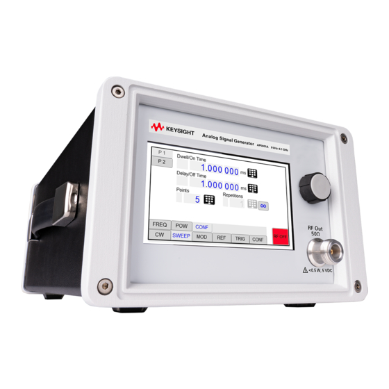
Keysight AP5001A/AP5002A Signal Generators User’s Guide Front Panel Operation The following topics can be found in this chapter: “RF 50 Ω Connector” on page 35 “Rotary Button” on page 35 “Front Panel Settings” on page 35 “CW Menu” on page 35 “Sweep Menu”... - Page 34 Front Panel Operation The front panel display allows you to access many of the AP5001A and AP5002A functions. However, the GUI interface allows you access all available functions. Figure 3-1 Front panel with touch display Keysight AP5001A/AP5002A Signal Generators User’s Manual...
-
Page 35: Rf 50 Ω Connector
SMB connector to provide the output for RF signals. The impedance is 50 The damage levels for RF and DC are specified in the data sheet. For AP5001A it is +27 dBm maximum and the allowed DC level is 5 V. -
Page 36: Sweep Menu
INFinite, and 1 (single repetition). The sweep is started by pressing the RF On/Off button. Figure 3-4 Front Panel Sweep > Frequency Display Keysight AP5001A/AP5002A Signal Generators User’s Manual... - Page 37 ALC can be set on or off. Use List Memory a to define each list point and load or save to List memory or Sent the List to RAM. Keysight AP5001A/AP5002A Signal Generators User’s Manual...
-
Page 38: Modulation Submenus
Modulation Submenus Pulse Modulation Submenu In the pulse modulation submenu the pulse width, pulse period and pulse trigger can be configured in the following tabs: — Main Figure 3-7 Modulation Pulse Submenu Main — CONFiguration Keysight AP5001A/AP5002A Signal Generators User’s Manual... - Page 39 Front Panel Operation Front Panel Settings Figure 3-8 Modulation Pulse Submenu Configuration — TRIGger Figure 3-9 Modulation Pulse Submenu Trigger — INFO Figure 3-10 Modulation Pulse Submenu Info Keysight AP5001A/AP5002A Signal Generators User’s Manual...
- Page 40 Modulation Analog Submenu FM PM (Phase) Modulation Submenu In the phase modulation submenu the internal and external phase modulation can be accessed. It is possible to change between internal and external modulation source and change modulation parameters. Keysight AP5001A/AP5002A Signal Generators User’s Manual...
-
Page 41: Reference Submenu
In the Reference menu the internal or external reference source and the reference output signal can be selected and configured. Figure 3-14 Reference Trigger Submenu Trigger In In this menu the trigger system can be configured like trigger source, trigger edge, etc. Keysight AP5001A/AP5002A Signal Generators User’s Manual... -
Page 42: Configuration
LF Generator is selected, you can configure the frequency, amplitude and waveform. Figure 3-16 Trigger Submenu Out (LF OUTPUT) Configuration The Configuration submenu is divided into the following tabs: — PRESet — COMMunication — DISPlay — INFO — TEST Keysight AP5001A/AP5002A Signal Generators User’s Manual... -
Page 43: Preset Settings Submenu
Info Submenu In the Info Submenu, information about the device is shown (serial number, firmware version, and options installed). Test Submenu The Test Submenu allows you to perform a self test on the instrument. Keysight AP5001A/AP5002A Signal Generators User’s Manual... - Page 44 Front Panel Operation Front Panel Settings Keysight AP5001A/AP5002A Signal Generators User’s Manual...
-
Page 45: Additional Information
Keysight AP5001A/AP5002A Signal Generator User’s Manual Additional Information “Remote Programming the Signal Generator” on page 46 “Maintenance and Warranty Information” on page 47... -
Page 46: Remote Programming The Signal Generator
The signal generator can be remotely programmed by using SCPI commands. Please refer to the Programmer’s Manual for details available on Keysight’s website. There are also examples in different programming languages that can be used. Keysight AP5001A/AP5002A Signal Generators User’s Guide... -
Page 47: Maintenance And Warranty Information
No other warranties are expressed or implied, including but not limited to implied warranties of merchantability and fitness for a particular purpose. Keysight is not liable for consequential damages. Keysight AP5001A/AP5002A Signal Generators User’s Guide... - Page 48 This information is subject to change without notice. © Keysight Technologies 2024 Edition 1, December 2024 AP5001-90002 www.keysight.com...
Need help?
Do you have a question about the AP5001A and is the answer not in the manual?
Questions and answers