
Related Manuals for Sony MAV-555A


Summary of Contents for Sony MAV-555A
- Page 1 MULTI ACCESS VIDEO DISK RECORDER MAV-555A INSTALLATION MANUAL 1st Edition Serial No. 10001 and Higher...
- Page 2 4. Prevention against achieving hazardous condition due to uneven mechanical loading When this product is installed in a rack, please make sure that the rack does not achieve hazardous condition due to uneven mechanical loading. MAV-555A...
-
Page 3: Table Of Contents
DPR-189A/189B Board ............2-2 (E) 2-2-2. DM-127 Board ..............2-3 (E) 2-2-3. EM-3 Board ................2-7 (E) 2-2-4. FM-81 Board ................ 2-9 (E) 2-2-5. FP-128 Board ..............2-13 (E) 2-2-6. IF-837 Board ..............2-14 (E) 2-2-7. PU-121 Board ..............2-15 (E) 1 (E) MAV-555A... -
Page 5: Manual Structure
Manual Structure Purpose of this manual This manual is the installation manual of the MAV-555A Multi Access Video Disk Recorder. This manual is intended for use by trained system and service engineers, and describes the information regarding installation. Related manuals Besides this Installation Manual, the following manuals are available for the MAV-555A. -
Page 7: Installation
Cautions when an error appears in a HDD . Treat this unit conform to the above cautions, even when an error appeared. . Keep the unit in the condition in which the error appeared, and record the details of the error. 1-1 (E) MAV-555A... -
Page 8: Installation Procedure
1-3. Operating Conditions and Installation Space The following flow chart shows the installation procedure 1-3-1. Operating Conditions of the MAV-555A. For details of each item, refer to the relevant section. 1. Set the operating temperature and humidity within the following conditions. - Page 9 . If the power is turned on with the cabinet is removed, the air-cooling effect of the fan will be greatly reduced, damaging the HDD or its data. Do not operate the unit with the cabinet is removed. 123.8 263.5 415.9 Unit : mm 1-3 (E) MAV-555A...
-
Page 10: Power Supply
AC inlet (MAV) Hole of the chassis Harness clamper 2 For customers in the United Kingdom. 1 Power cord : ! 1-782-929-11 2 Plug holder : 3-613-640-01 Safety earth (Green/Yellow) AC inlet (MAV) Live (Brown) Neutral (Blue) 1-4 (E) MAV-555A... - Page 11 (CN7, CN9, CN11, CN13) of the BKMA-540. 7. Insert the other ends of the cables to the connectors of the main unit. BKMA-540 Original cable ([BLU]) Connectors of of the main unit the main unit CN13([RED]) CN111([BLK]) CN9([ORG]) CN7([YEL]) 1-5 (E) MAV-555A...
- Page 12 (four cables) Harness Cut here clamper 2 Fig. 2 View from the top 2 to 3 mm Re-usable band Harness clampers For all the procedures after installation of the BKMA-540 is completed, refer to the BKMA-540 Installation Manual. 1-6 (E) MAV-555A...
- Page 13 When installing the circuit board, push the two board levers at the same time. Be careful not to pinch the cables. Board levers For all the procedures after installation of the BKMA-560 is completed, refer to the BKMA-560 Installation Manual. 1-7 (E) MAV-555A...
-
Page 14: Rack Mounting
: 4 pcs . Ornamental washer : 4 pcs Outer rail Standard tightening torque Inner rail Screw size Standard tightening torque M3.0 0.7 to 1.0 N.m (7 to 9 kgf.cm) M4.0 1.2 to 1.6 N.m (12 to 16 kgf.cm) 1-8 (E) MAV-555A... - Page 15 Tighten the screws of the bracket that were temporary tightened in step 1. Rack angle 4 x 16 Rack mounting surface Rack angle PSW4 x 16 50 to 55 mm Outer rail 1 1-9 (E) MAV-555A...
- Page 16 2. Attach the rack angles to the rack with screws and ornamental washers. Secure the rack angles to the rack with the screws. Other- wise the unit may slide and fall off, resulting in injury. Rack angle Ornamental washers RK5 x 14 RK5 x 14 Ornamental washers 1-10 (E) MAV-555A...
-
Page 17: Signal Input And Output
1 Vp-p, 75 Z (Sync negative) (XLR 3-pin, male) AUDIO L : +4 dBm/ 600 Z load, Low impedance, Unbalanced AUDIO R : +4 dBm/ 600 Z load, Low impedance, Unbalanced HEAD PHONES (JM-60) _12 dBu (8 Z), Unbalanced 1-11 (E) MAV-555A... - Page 18 RX (+) TX (_) RX4 _ TX4 _ ETHER : 10BASE-TX (8-pin modular jack) RVD _ +12 V < External View > Pin No. Signal TX + TX _ RX + RXCT RXCT RX _ TXCT TXCT 1-12 (E) MAV-555A...
- Page 19 Ref Frame Pulse width : 30 ms or more Command Input (PLAY) 200 lines 100 lines There must be a falling edge of the command between here. 4 Frames A/V Output Invalid Valid Valid Valid Status Output (PLAY) 1-13 (E) MAV-555A...
-
Page 20: Connecting Connectors And Cable
When connecting cables to various connectors on the rear panel, connect the following connectors/cable or their equivalent. MAV-555 Matching Connector/Cable Panel Indication Connector Connector Sony Part No. VIDEO IN (COMPOSITE) BNC, 75 Z BNC, 75 Z 1-569-370-12 VIDEO OUT (COMPOSITE) 5C-2V cable... -
Page 21: Settings Upon Completion Of Installation
R1 00 : 00 : 00 : 00 P1 00 : 00 : 00 : 00 010-525/625 R2 00 : 00 : 00 : 00 P2 00 : 00 : 00 : 00 Execute 7. Turn the VIDEO/MENU knob and select “YES”. 010-525/625 Execute [SET] 8. Press the SET button. 1-15 (E) MAV-555A... -
Page 22: Setting The Operation Mode
“Delete All Materials” of the hard disk drive. (Refer to Section 1-9-1.) To re-start the system swiftly, execute [027-FAST REBOOT] from the setup menu. 9. Turn off the main power once. To re-start the system swiftly, execute [027-FAST REBOOT] from the setup menu. 1-16 (E) MAV-555A... -
Page 23: Setting The Setup Level
GATEWAY” of the set up menu in the same way. 10. Turn off the main power. 11. Set the switch S501-1 on the EM-3 board back to the OFF position. 1-9-7. System Time Settings Refer to Section 3-4-5 in the Operation Manual. 1-17 (E) MAV-555A... -
Page 24: Attaching The Seal
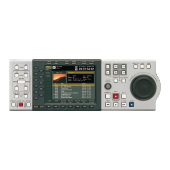
1-10. Attaching the seal 1-10. Attaching the Seal When the BKMA-505 is used as the control panel of the MAV-555A, attach the seal at the specified position as shown below. Seal TC / UB TIMER SEL SHUTTLE PORT SELECT PLAYER... -
Page 25: Service Overview
(A). Control panel 4. Remove the dust that has accumulated on the filter blank panel with a vacuum cleaner. 5. Attach the air filter (A) and control panel or blank panel. 2-1 (E) MAV-555A... -
Page 26: Description Of Internal Switches And Indicators
Flashes after the completion of FPGA (IC355) initialization. D604 (B-3) Green Lights up after the completion of FPGA (IC606) initialization. D605 (A-2) Green Lights up after the completion of FPGA (IC647) initialization. D900 (B-3) Green Flashes after the completion of FPGA (IC917) initialization. 2-2 (E) MAV-555A... -
Page 27: Dm-127 Board
S52-5 : Not used. S52-6, 7 : Selects the CPU startup mode. OFF OFF : Normal operation mode OFF : TFTP server mode OFF ON : HOST debugging mode ON : Configuration mode S52-8 : Not used. 2-3 (E) MAV-555A... - Page 28 S53-5 : Not used. S53-6, 7 : Selects the CPU startup mode. OFF OFF : Normal operation mode OFF : TFTP server mode OFF ON : HOST debugging mode ON : Configuration mode S53-8 : Not used. 2-4 (E) MAV-555A...
- Page 29 FPGA (IC420) initialization. D660 (B-1) Green Config-4 Flashes after the completion of FPGA (IC660) initialization. D770 (D-5) Green Config-5 Flashes after the completion of FPGA (IC770) initialization. D800 (C-5) Green Config-6 Flashes after the completion of FPGA (IC800) initialization. 2-5 (E) MAV-555A...
- Page 30 An example when D50 to D53 and D58 to D61 are turned on, is shown in the following illustration. : Lights up : Lights off D50 ----------------- D61 Operating status of D54 to D57, D62 to D65 CLOSE STOP MUTE STILL PLAY SHUTTLE SEND RECEIVE COMPILE COPY 2-6 (E) MAV-555A...
-
Page 31: Board
ON : Configuration mode OFF : HOST debugging mode OFF ON : TFTP server mode OFF OFF : Normal operation mode S501-8 : Boot SEQ execution mode. OFF : Normal mode ON : No booting (for debugging) 2-7 (E) MAV-555A... - Page 32 : Lights off D501----------------- D508 Operating status Boot Check RAM memory Test Bank5 setup Bank7 setup Program Loader P-Falsh AP startup processing Compatibility setup with the Ver 1.0x series Data, BSS area initialization AP execution RAM Error No Program 2-8 (E) MAV-555A...
- Page 33 Reset switch (A-RES) Initializes all boards. S402 (E-1) Battery switch Sets the ON/OFF of the backup [OFF] [ON] battery. ON : Normal mode OFF : For storage as the repair parts S600 (D-1) Reset switch (T-RES) Initializes FM boards (TM part) 2-9 (E) MAV-555A...
- Page 34 OFF OFF : Normal operation mode OFF : TFTP server mode OFF ON : HOST debugging mode ON : Configuration mode S750-8 : Selects the LED display modes. OFF: Normal mode System indication mode (Refer to “LEDs” in this section) 2-10 (E) MAV-555A...
- Page 35 D755 (B-1) Green TM-LED (reserved) D756 (B-1) Green TM-LED (reserved) D757 (B-1) Green TM-LED Lights up when the control panel is the Front Control. D758 (B-1) Green TM-LED (LSB) Lights up in the 525/60 mode. 2-11 (E) MAV-555A...
- Page 36 Boot Check RAM memory Test FM : 2nd DRAM setup FM : SDRAM UPMB setup Program Loader P-Falsh AP startup processing Compatibility setup with the Ver 1.0x series Data, BSS area initialization AP execution RAM Error No Program 2-12 (E) MAV-555A...
-
Page 37: Fp-128 Board
D102 (F-3) Green Flashes when the command is sent to Flashes the EM board. D103 (F-3) Green Flashes when data is written to the FL tube. Flashes D104 (F-3) Lights up when an error occurs. Lights off 2-13 (E) MAV-555A... -
Page 38: If-837 Board
(E-2) Green Flashes when initialization of the FPGA (IC1801) is completed. D2301- 2305 (F-2) Green Flashes when initialization of the FPGA (IC2201) is completed. D2701- 2705 (G-2) Green Flashes when initialization of the FPGA (IC2601) is completed. 2-14 (E) MAV-555A... - Page 39 OFF : 18 GB OFF : 9 GB S1101-3, 4, 5 : Not used. S1101-6, 7, 8 : Sets the mode. (S1101-6 is fixed to OFF) : Normal condition : DIAG mode : BSPS dialog display1 : BSPS dialog display2 2-15 (E) MAV-555A...
- Page 40 HDD installed. OFF ON : 36 GB Default setting of S1102-8 ON OFF : 18 GB in MAV-555A is set to OFF . OFF OFF : 9 GB S1102-3 to 7 : Not used. S1102-8 : Sets the mode.
- Page 41 Lights up while downloading to the FPGA is in progress. D1801 (A-1) Green For testing D1802 (A-1) Green For testing D1803 (A-1) Green For testing D1804 (A-1) Green For testing D1809 (A-2) Green Lights up while downloading to the FPGA is in progress. 2-17 (E) MAV-555A...
- Page 43 The material contained in this manual consists of information that is the property of Sony Corporation and is intended solely for use by the purchasers of the equipment described in this manual. Sony Corporation expressly prohibits the duplication of any portion of this manual or the use thereof for any...
- Page 44 Printed in Japan Sony Corporation MAV-555A (SY) J, E 2001. 6 16 B&P Company 3-205-799-01 ©2001...
Need help?
Do you have a question about the MAV-555A and is the answer not in the manual?
Questions and answers