Table of Contents
Advertisement
Quick Links
Advertisement
Table of Contents

Related Manuals for INSTEON On/Off Outlet


Summary of Contents for INSTEON On/Off Outlet
- Page 1 On/Off Outlet On/Off Outlet Owner’s Manual Owner’s Manual...
-
Page 2: Table Of Contents
Installation Timeline Installation Installation Diagrams End-of-Run Outlet Middle-of-Run Outlet Switched Outlet INSTEON Links Understanding Linking Adding to the INSTEON Hub Software-Only Features Beep on Button Press Blink on Traffic Disable Local Programming Error Blink LED Brightness Local Programming Flow Chart... -
Page 3: Getting Started
Getting Started Getting Started Everything you need to quickly get up and running. Everything you need to quickly get up and running. -
Page 4: Insteon Wall Outlet
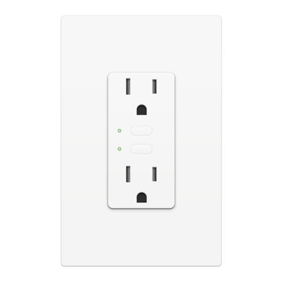
INSTEON Wall Outlet On/Off Outlet Buttons Tap to turn the upper outlet on or off. See sections on Basic Linking and Status LEDs Upper Upper Local Programming for additional set Outlet button functions. Tamper Resistant Tap to turn the lower outlet on or off. -
Page 5: Installation Timeline
Installation Timeline Installation Timeline Unbox and read instructions Unbox and read instructions Disconnect Power Disconnect Power Remove the old outlet Remove the old outlet Reconnect Power Reconnect Power Identify Line wire Identify Line wire Disconnect Power Disconnect Power Connect the outlet wires to Connect the outlet wires to the junction box wires the junction box wires... -
Page 6: Installation
Installation Disconnect Power Remove the Old Outlet Turn off power to your outlet at the Remove the old outlet and disconnect electrical service panel. the wires. Circuit Breakers Fuse Panel ½” 12mm Reconnect Power Identify Line Turn on power at the circuit breaker. Use a voltage detector to identify the line wire. - Page 7 Installation Wire-In the Outlet Turn off power at the circuit breaker. Connect the Outlet wires to the identified wires in the junction box. Verify that the wire nuts are secure and that no exposed copper wire is visible. Additional wiring diagrams can be found in the Installation Diagrams section.
- Page 8 Test your Outlet by tapping one of the Complete installation by reattaching set buttons to turn On and Off. your wall plate. For the best look, us an INSTEON Screwless Wall Plate. Installation of your Wall Outlet is now complete.
-
Page 9: Installation Diagrams
Installation Diagrams Installation Diagrams Use the installation diagrams in this section to help you wire Use the installation diagrams in this section to help you wire your Wall Outlet. your Wall Outlet. -
Page 10: End-Of-Run Outlet
End-of-Run Outlet Line Neutral Ground... -
Page 11: Middle-Of-Run Outlet
Middle-of-Run Outlet Line Neutral Ground... -
Page 12: Switched Outlet
Switched Outlet Without INSTEON Wall Switch Replacing a switched outlet requires removing the wall switch from the circuit. The wall switch can be replaced by an INSTEON Wall Switch or Keypad if control is still desired. Neutral Line Ground Line... - Page 13 Switched Outlet With INSTEON Wall Keypad Line Neutral Ground Line Neutral Ground...
-
Page 14: Insteon Links
INSTEON Links Chapter explanation INSTEON devices can stand alone and function as a local switch or INSTEON devices can stand alone and function as a local switch or dimmer, but their real power comes when they are connected together to dimmer, but their real power comes when they are connected together to form a control system. -
Page 15: Understanding Linking
Switch B cannot turn Switch A on or off. 75% brightness. Controllers Responders INSTEON devices that can turn other devices INSTEON devices that receive the command of a on or off are called controllers. controller are called responders. Sensors, Switches, Keypads and the Switches, Keypads, Plug-In Modules and Hub are common controllers. - Page 16 Understanding Linking Controller-Only Responder-Only Some devices, like sensors, can only control Some devices cannot control other devices; other devices. these devices only receive INSTEON commands. Motion Sensor Dimmer Switch LED Bulb Dimmer Switch The Motion Sensor will turn on the Switch...
-
Page 17: Adding To The Insteon Hub
Adding to the INSTEON Hub Tap the Add a Device button. Android Windows Phone Open the drawer by Navigate to All Devices Navigate to All Devices swiping from the right from Rooms on your from Rooms on your side of your iOS device... - Page 18 Software-Only Features Software-Only Features Chapter explanation Most INSTEON devices contain features that can only be enabled, Most INSTEON devices contain features that can only be enabled, disabled or modified using INSTEON control software such as HouseLinc disabled or modified using INSTEON control software such as HouseLinc and an INSTEON PowerLine Modem.
-
Page 19: Software-Only Features
Blink on Traffic The Wall Outlet will beep every time one of its The Wall Outlet LED will blink if it detects buttons are tapped. By default, this feature is INSTEON communication. By default, this disabled. feature is disabled. Disable Local Programming... -
Page 20: Led Brightness
Software-Only Features LED Brightness Adjust the brightness of the status LEDs from full bright to off. -
Page 21: Local Programming
Chapter Title Local Programming Local Programming Chapter explanation Encompassing all on-device programming options, use the local Encompassing all on-device programming options, use the local programming to set local properties and factory reset. For the best programming to set local properties. For the best experience, use experience, use software for managing device properties. - Page 22 Unlinking Mode exit unlinking mode after a link has been removed from another INSTEON device. Allows the removal of multiple links from the INSTEON device. The device will stay Multi-Unlinking Mode in unlinking mode for 4 minutes or until the device’s set button is tapped.
-
Page 23: Flow Chart
Flow Chart Linking Mode Unlinking Mode Press Press Multi-Linking Multi-Unlinking Mode Press Mode Press Select Exit Exit Select Exit Exit... -
Page 24: Led Brightness
LED Brightness Upper set button only For a bright status Linking Mode Unlinking Mode Status LED LED, make sure the Brightness Press Press upper LED is green. Bright Bright For a dim status Linking Mode Unlinking Mode Status LED LED, make sure the Press Press Brightness... -
Page 25: Load Sense
Load Sense Enable Linking Mode Enable Load Sense Load Sense Disable Linking Mode Disable Load Sense... -
Page 26: Soft Factory Reset
Soft Factory Reset Upper and lower set buttons A Soft Factory Reset will erase all device settings including any links made with the top and bottom outlets. If On/Off Outlet does not respond, attempt the Alternate Factory Reset. Linking Mode Unlinking Mode... -
Page 27: Factory Reset
Chapter Title Factory Reset Factory Reset Chapter explanation A factory reset will erase all links stored in the device’s database as well as A factory reset will erase all links stored in the device’s database as well as any customized properties. any customized properties. -
Page 28: Factory Reset
Factory Reset Alternate Procedure Press and hold the upper set Factory Reset will erase all device button. settings including any links made with the top and bottom outlets Turn off power to your outlet at the electrical service panel. Circuit Breakers Fuse Panel An assistant will be required to turn power on and off at the service panel. -
Page 29: Appendix
Appendix Appendix Everything else you might need to know about your INSTEON product. Everything else you might need to know about your INSTEON product. -
Page 30: Specifications
Setup Memory Non-volatile EEPROM Status LED Red/Green LEDs INSTEON Features INSTEON Device Category 0x02 INSTEON Device Subcategory 0x39 INSTEON ID INSTEON Links INSTEON Messages Repeated INSTEON Minimum Receive Level 10 mV INSTEON Minimum Transmit Level 3.2 Vpp into 5 Ohms... - Page 31 INSTEON Powerline Device INSTEON Powerline Frequency 131.65 KHz INSTEON RF Device Maximum Controlled Scenes Maximum Scene Memberships RF Beacon Radio Frequency 915.0 MHz US/Canada Radio Frequency Range Up to 250 feet Software Configurable Mechanical Beep on Button Press Yes, Software configurable...
- Page 32 Electrical Power Consumption <0.4 Watts Supply Voltage 120 Volts AC, 50/60 Hertz, single phase Surge Resistance Surges over 1000 volts Power Connector NEMA 5-15R Certification FCC ID Part 15B & 15C IC RSS-210 Issue 8 UL-498 Safety standard for receptacles CSA C22.2 #42 Including sections 131-135 for tamper-resistant outlets UL-244A, CAN/CSA C22.2#14 Standard for solid-state...
-
Page 33: Troubleshooting
Try this: • Check to make sure power is flowing to your INSTEON Wall Outlet. If your outlet was just installed, make sure the circuit breaker controlling the switch has been turned on. It is also advisable to verify the wire connections in the junction box are secure and not showing any bare wire. - Page 34 Try this: • Make sure the Wall Outlet’s connected load is on and then re-link the device to your INSTEON controller. This link will overwrite the previous “off” link. The Wall Outlet does not respond to button taps or controller links A power surge or excessive powerline noise may have caused the outlet to unexpectedly stop responding.
-
Page 35: Certifications And Warnings
To minimize heat buildup, ensure the area surrounding this product is as clear of clutter as possible. • Each INSTEON product is assigned a unique INSTEON I.D., which is printed on the product’s label. • To reduce the risk of overheating and possible damage to other equipment, do not use this product to control loads in excess of the specified maximum(s) or, install in locations with electricity specifications which are outside of the product’s specifications. -
Page 36: Product Warranty
You may also have other legal rights that may vary from state to state. Protected under U.S. and foreign patents (see www.insteon.com/patents) © 2014 INSTEON Rev 10.31.14...
Need help?
Do you have a question about the On/Off Outlet and is the answer not in the manual?
Questions and answers