Table of Contents
Advertisement
Quick Links
Advertisement
Table of Contents

Subscribe to Our Youtube Channel
Summary of Contents for MBT Vaca Shape
- Page 1 User Manual...
-
Page 2: Table Of Contents
Content Chapter 1 Equipment Parts ....................1 1.1 Parts ........................1 1.2 Packing List ......................2 Chapter 2 Safety ........................3 2.1 Optic Safety ......................3 2.2 Operation Safety ..................... 3 2.3 Safety Signs ......................4 2.4 Environmental Request ..................4 Chapter 3 Technical Specifications………………………………………………………….. -
Page 3: Chapter 1 Equipment Parts
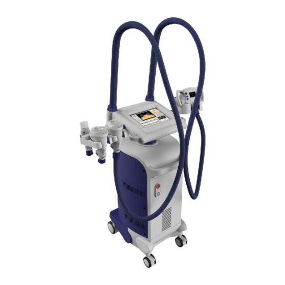
Chapter 1 Equipment Parts 1.1 Parts Handpiece 2 Handpiece 1 Handpiece 4 Handpiece 3 10.4 inch touch color screen Emergency switch Power switch Fuse Fuse Footswitch Electricity breaker Earth ground Power supply 1//22 All rights reserved... -
Page 4: Packing List
Packing List The host×1 Handpiece 1×1 Handpiece 2×1 Handpiece 3×1 Power line×1 Handpiece 4×1 Quick plug×2 Handpiece stand-Left Filter element O Shape ring×10 Fuse×2 extractor×1 Handpiece stand-Right Grounding wire×1 Footswitch×1 Key card×1 Blank card×2 User manual×1 2//22 All rights reserved... -
Page 5: Chapter 2 Safety
Chapter 2 Safety The operators and maintenance person shall be familiar with the safety requirements and procedures when they use the equipment. Optic Safety 1) The local power supply shall be AC230V±10%,50Hz±1Hz/AC110V±10%,60Hz±1Hz; 2) 5 minutes later after unplug the power plug, you can make maintenance. Never leave the machine with cover open, or there will be danger to the personnel or the equ ipment;... -
Page 6: Safety Signs
Safety Signs means grounding 2) “AC220V”or “AC110V” means rated input voltage; 3) “AC250V 10A” is the fuse model and rating; Picture 2.2-2 Picture 2.2-3 2.4 Environmental Request Air quality: System shall work in the environment which has no corrosive substances, like acid, dust and so on; Temperature and humidity:... -
Page 7: Chapter 3 Technical Specifications
Chapter 3 Technical Specifications Items Specifications Screen 1. The host screen: 10.4 inch TFT color touch screen 2. Handpiece 1 screen: 2.5 inch 3. Handpiece 2 screen: 1.0 inch 4. Handpiece 3 screen: 1.0 inch Safety test Real time online for safety test Vacuum pressure 1) Absolute value: 15kPa -90kPa ;... -
Page 8: Chapter 4 Installation
Chapter 4 Installation Handpiece Installation and Disassemble Picture 4.1-1 Picture 4.1-2 1) Insert handpiece stand into A (Picture 4.1-1); 2) You will hear the sound, which means it is fixed well on the equipment; 3) Disassemble: Pull the handle(Picture 4.1-2), at the same time, take out the handpiece stand;... -
Page 9: Connect The Handle With Fast Connector
4.3 Connect the Handle with Fast Connector Handle Fast connector Picture 4.3-2 Picture 4.3-1 1) Connect the handle with fast connector like Picture 4.3-1 shows; 2) Fix the nut(Picture 4.3-2) 4.4 Change the Tip of Handpiece 4 Picture 4.4-1 Picture 4.4-2 Handpiece 4 has 2 tips, one is bigger and the other is smaller. -
Page 10: Chapter 5 Operation
Chapter 5 Operation 5.1 Start Equipment 1) Connect power supply, turn on electricity breaker, press power switch; 2) The initialization lasts for 5s(Picture 5.1-1); P icture 5.1 -1 If the handpiece lights, i t m eans handpiec e is well connec ted. 5.2 Handpiece 1 Picture 5.2-1 In Picture 5.2-1:... - Page 11 Picture 5.2-2 In Picture 5.2-2: 1) A area:If handpiece 1 is connected, touch it; 2) B area: shows working mechanism of handpiece 1; 3) C area: shows the defaulted parameters of handpiece 1: i. To adjust cavitation power: Touch and it turns to ;...
-
Page 12: Handpiece 2 And Handpiece 3
5) F area shows its available treatment parts. Touch the picture you want and the treatment manner will be showed at B area; 6) G area adopts countdown. Press to adjust time; 7) D area shows timing function of IC card. Issue a user card referring to 5.5.1;... - Page 13 Picture 5.3-2 Picture 5.3-3 In Picture 5.3-2: System will check online for handpiece connection. Touch the handpiece you want in A area; F area: Touch treatment item in F area, for example, will change to . At the same time, B area will show relative treatment manner (Picture 5.3-3).
-
Page 14: Handpiece 4
5.4 Handpiece 4 Picture 5.4-1 In Picture 5.4-1: A: “-” key B: “o” key C: “+” key Press “+”“-” key to adjust vacuum(A ,C) ; Then press “o”(B) to be ready for treatment; You can adjust it on the host screen; Parameters could not be adjusted during ready;... -
Page 15: Ultrasonic Frequency
Make unlock card touch response area of the equipment; C area: shows duration and vacuum of handpiece 4. 5.5 Ultrasonic Frequency Picture 5.5-1 Picture 5.5-2 After you change the power supply, ultrasonic handpiece, or find energy increase or decrease, you shall adjust the frequency. -
Page 16: Issue User Card
5.6.1 Issue User Card Picture 5.6-1 Picture 5.6-2 After initialization, insert the key card (Picture 5.6-1)and screen shows Picture 5.6-2; 2) In Picture 5.6-2: Press “+” or “-” key to issue time, 10 minutes for each press, 100 minutes for continual press; The scope is 0-99900 minutes. -
Page 17: Ic Card Applications
You can issue many unlock cards at a time; Press to exit issuing interface; 5.6.3 IC Card Applications 1. For agency The agency can rent equipments for marketing and charge according to using time; For example, the agency charges for 14400 minutes=30 days×8 hours/day×60 minutes/hour once: Ø... -
Page 18: Chapter 6 Maintenance
Chapter 6 Maintenance Turn off the equipment and 5 minutes later you can maintenance this equipment. Never leave the equipment with cover open and no personal care, or there will be danger to personnel or system. The maintenance of inner parts of the equipment shall be carried out by professional technical persons. 6.1 Daily Maintenance 1. -
Page 19: Change Filter Element Of Equipment
4) Dry the place with warm wind where you could not touch; Picture 6.1-5 6.2 Change Filter Element of Equipment 1) When the equipment works for one or two months, you have to change for new filter elements; 2) Unscrew A and B on the back of the equipment(Picture 6.2-1)and take out the filter elements; 3) Put a new filter element on A/B;... -
Page 20: Chapter 7 Troubleshooting
oting Chapter 7 Troublesho 7.1 Guarantee The misusing or modifying may make the guarantee invalid. 7.2 Troubleshooting Trouble Reason Measures Trouble with power switch Contact with us Didn’t insert power wire well Well insert the power wire Start equipment failure Fuse is broken Change the fuse Trouble with controlling board... -
Page 21: Chapter 8 Clinical Guide
Chapter 8 Clinical Guide 8.1 Working Mechanism a) Ultrasonic heat penetration plus massage manner; 1M cavitation heats fat and fat cells precipitate fat; the fat goes into lymphatic system; massage manner helps to discharge toxin and fat, promote blood circulation; b) Handpiece 1 working mechanism:40KHz cavitaiton shakes fat cells;... -
Page 22: Treatment Manner
Handpiece 4 Belly Back Shoulder and Nek Vacuum (Big tip) Vacuum (Small tip) Duration Step by step 2s/ Slide 3-7s 8.6 Treatment Manner Belly, hip, thigh Procedure Parts Handpiece 1 Handpiece 2 Handpiece 4 Handpiece 1 Belly 30-40 minutes 15-20 minutes 5-8 minutes 15-20 minutes 15-20 minutes... -
Page 23: After Treatment
Parts Procedure Handpiece 2 Handpiece 3 Breast Handpiece 2 30-40 minutes Face Handpiece 3 30-40 minutes Note: One course contains 10 times; different customer adopts different courses. 8.6 After Treatment 1) Do not use cold water to wash treated skin in 8 hours after treatment; 2) Do not massage on treated skin;... - Page 24 If customer wants to get very good effect, he has to accept treatment according to treatment course; More or less 1-2 months later, the customer will see the evident effect; Thigh circumference reduces 1-5cm; waist circumference reduces 2-6cm; most parts circumference reduce 2-3cm) Question:Is this equipment safe? What’s the clinical feeling? Answer:...
Need help?
Do you have a question about the Vaca Shape and is the answer not in the manual?
Questions and answers