
Related Manuals for Gossen MetraWatt METRALINE ISO CHECK


Summary of Contents for Gossen MetraWatt METRALINE ISO CHECK
- Page 1 Operating Instructions CHECK METRALINE 3-349-691-03 Insulation Resistance Tester 2/4.13...
-
Page 2: Table Of Contents
Table of Contents Meanings of Symbols on the Instrument Page This device is equipped with double or reinforced insula- tion. Introduction ..............2 Scope of Delivery ................2 Danger of injury due to electrical current, Optional Accessories ..............2 warning regarding dangerous electrical voltage Safety Precautions .................2 Applications ..................3 Warning concerning a source of danger... -
Page 3: Applications
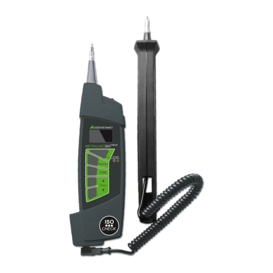
Applications The test instrument consists of a compact housing with a pat- ented means of retaining the second test probe. The high-contrast, four-color OLED display assures excellent legi- bility. When performing measurements under unfavorable light conditions, measuring point illumination can be switched on – white LED at the front. -
Page 4: Performing Measurements
Performing Measurements Measuring Functions Switching the Instrument On and Off, Energy-Saving Attention! Mode, Automatic Shutdown • Each time before measuring insulation resistance or surge The instrument is switched on by pressing and holding the START protection, make sure that the device under test is voltage- key. -
Page 5: Insulation Resistance Measurement
➭ Read the measured insulation resistance value. 3.3.2 Insulation Resistance Measurement ➭ Switch insulation measurement on by pressing the R Note key. The device under test may not be disconnected from the test instrument as long as the “!” warning symbol is lit up. Discharging large capacitances may take several tens of seconds! Figure 3.7:... -
Page 6: Further Device Functions
If the symbol is included in the description of the surge pro- After insulation measurement has been completed, any remaining tection device, the manufacturer’s instructions must be observed residual voltage is displayed as U , which may result from cable for the respective device type. -
Page 7: Device Reset Function
Device Reset Function Ambient Conditions If the test instrument does not function as described in these Operating Conditions instructions, we recommend a device reset. The test instrument Operating temperature0 to 40° C must be switched off and neither of the test probes may be con- Relative humidity Max. -
Page 8: Recharging The Batteries
5.1.2 Recharging the Batteries instrument is used primarily in the laboratory and indoors without considerable climatic or mechanical stressing, a calibration inter- val of once every 2 to 3 years is sufficient as a rule. Attention! During recalibration at an accredited calibration laboratory Use only the charger (Z507A) which is offered as an op- (DIN EN ISO/IEC 17025), deviations from traceable standards tional accessory for this instrument to charge the batter-...
Need help?
Do you have a question about the METRALINE ISO CHECK and is the answer not in the manual?
Questions and answers