
Subscribe to Our Youtube Channel
Related Manuals for Gossen MetraWatt METRALINE PAT


Summary of Contents for Gossen MetraWatt METRALINE PAT
- Page 1 Operating Instructions METRALINE PAT 3-447-022-03 Test Instrument for DIN VDE 0701-0702 2/4.19...
-
Page 2: Table Of Contents
Table of Contents Page Page Safety Precautions ........3 10.3.3 – Probe-Probe (GND) ......... 25 10.4 AKTIV - Function Test and Leakage Current General ..............3 Measurements ........... 26 Meanings of Symbols on the Device .......4 10.5 U – Testing the DUT (ELV) in the Presence of Line Meanings of Symbols in the Voltage .............. -
Page 3: Safety Precautions
Attention! General Before connecting a DUT, absence of voltage in the protective The METRALINE PAT test instrument has been conductor at the connection must be manufactured and tested in accordance with verified by touching the finger con- the following safety regulations: tact. -
Page 4: Meanings Of Symbols On The Device
Meanings of Symbols on the Device 300 V CAT II Maximum permissible voltage and Warning: Voltage! measuring category between con- Do not connect the device under test nections and ground to the test socket until it has been as- sured that the mains connection is in Warning concerning a point of safe working order. -
Page 5: Applications
Applications Standard Equipment and Acces- sories The METRALINE PAT tester is a measuring instrument for checking the effectiveness of Scope of Delivery protective measures in electrical devices in 1 METRALINE PAT test instrument accordance with DIN VDE 0701-0702. 1 Red measurement cable with safety plug... -
Page 6: Connection, Control And Display Elements
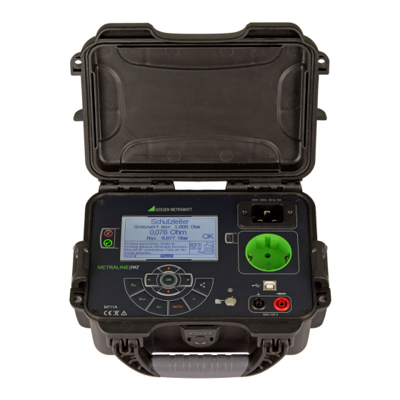
Connection, Control and Display Elements 1 Mains connection, IEC 60320 C19 Mains Connection (1), Finger Contact (7, 8) The corresponding warnings in section 1, 2 Test socket the warnings on the mains adapter cables 3 Glow lamp indicates and the warnings on any utilized accessories “line voltage at the test socket”... -
Page 7: Functions Description
Functions Description Attention! Power Supply Dangerous contact voltage may be present at defective DUTs when The device is powered by mains voltage (230 V 10%). they’re connected to a test socket, or at accessible conductive parts that The measuring electronics are protected by are not connected to the protective means of an internal fuse. -
Page 8: Bluetooth Interface
The Bluetooth interface is used to transfer In accordance with the legally applicable measurement data. requirements (accident prevention regula- The METRALINE PAT test instrument is tions, valid standards), the operator is equipped with a Bluetooth module for wire- responsible for the safety of electrical sys-... -
Page 9: Connection Display
check again at another power outlet. If Display and Menu Structure the device works at the second outlet, User prompting, measuring functions, limit arrange to have the first outlet checked values and measured values appear conve- by a qualified electrician. niently at the display. -
Page 10: Data Transmission
Bluetooth interface to an Android device to Function which ELEXONIQ has been installed (Android /RPE Protective conductor resistance app for METRALINE PAT). The data can be measurement subsequently transferred from the Android Insulation resistance measure- app to a PC, where they can be imported... -
Page 11: Rsl / Rpe - Protective Conductor Resistance
10.1 / RPE – Protective Conductor Resistance Definition Notes Insulation resistance and/or leakage current must be measured at all exposed, conduc- tive parts for protection category II and III devices, as well as for battery powered devices. Batteries must be disconnected during test- ing of battery powered devices. -
Page 12: Rpe - Connecting Protection Class I Devices To The Test Socket
10.1.2 RPE – Connecting Protection Class I Devices to the Test Socket Connection ➭ Connect the probe to the red probe socket. ➭ Insert the test object’s mains plug into the test socket. ➭ Switch the device under test on. Procedure ➭... -
Page 13: Rpe - Permanently Connected Duts
10.1.3 RPE – Permanently Connected DUTs Connection ➭ Connect the probe to the red probe socket. ➭ Switch the device under test on. Procedure ➭ Press the R key. ➭ Select the “Permanent Connection” menu with the help of the scroll keys. -
Page 14: Rpe - Probe-Probe Measurement
10.1.4 RPE – Probe-Probe Measurement Connection ➭ Connect the first probe to the black GND socket. ➭ Connect the second probe to the red probe socket. ➭ Switch the device under test on. Procedure ➭ Press the R key. ➭ Select the “Probe-Probe” menu with the ... -
Page 15: Rpe - Balancing The Probe Cable For The
10.1.5 RPE – Balancing the Probe Cable for the Protective Conductor Measurement This menu makes it possible to balance the probe cable’s resistance value. The maximum offset value, which is sub- tracted from subsequent measured values, must not exceed 0.100 . Connection ➭... -
Page 16: Riso - Insulation Resistance
10.2 – Insulation Resistance Definition Observe the following safety instructions for the connections listed below: • Probe-PE • PE grounded via parallel-contact earth- ing switch • Probe-Probe, if one side is grounded Warning: Voltage! Insulation Resistance Measurement Protection Category I Testing is conducted with up to Insulation resistance is measured between 500 V. -
Page 17: Riso - Ln-Pe
10.2.1 RISO – LN-PE Connection ➭ Insert the test object’s mains plug into the test socket. Procedure ➭ Press the R key. ➭ Select the “LN-PE” menu with the help of scroll keys. ➭ Start the measurement by pressing the OK key. -
Page 18: Riso - Ln-Probe
10.2.2 RISO – LN-Probe Connection ➭ Insert the test object’s mains plug into the test socket. ➭ Connect the probe to the red probe socket. Procedure ➭ Press the R key. ➭ Select the “LN-Probe” menu with the help of the scroll keys. -
Page 19: Riso - Probe-Pe
10.2.3 RISO – Probe-PE Connection ➭ Insert the test object’s mains plug into the test socket. ➭ Connect the probe to the red probe socket. Procedure ➭ Press the R key. ➭ Select the “Probe-PE” menu with the help of the scroll keys. -
Page 20: Riso - Probe-Probe (Gnd)
10.2.4 RISO – Probe-Probe (GND) Insulation Resistance Measurement, PC III Connection ➭ Connect the first probe to the black GND socket. ➭ Connect the second probe to the red probe socket. ➭ Connect phase conductors L1, L2 and L3 to N and the red probe. ➭... -
Page 21: Riso - L-N
10.2.5 RISO – L-N Connection ➭ Insert the test object’s mains plug into the test socket. ➭ Connect the probe to the red probe socket. Procedure ➭ Press the R key. ➭ Select the “L-N” menu with the help of ... -
Page 22: Iea - Equivalent Leakage Current Measurement
10.3 – Equivalent Leakage Current Measurement Warning: Voltage! Equivalent Leakage Current Measure- General ment Measurement of equivalent leakage current Testing is conducted with up to is stipulated by DIN VDE 0701-0702 after 250 V. Current limiting is utilized the insulation test has been passed. (I <... -
Page 23: Iea - Ln-Pe
10.3.1 I – LN-PE Connection ➭ Insert the test object’s mains plug into the test socket. Procedure ➭ Press the I key. ➭ Select the “LN-PE” menu with the help of scroll keys. ➭ Start the measurement by pressing the OK key. -
Page 24: Iea - Ln-Probe
10.3.2 I – LN-Probe Connection ➭ Insert the test object’s mains plug into the test socket. ➭ Connect the probe to the red probe socket. Procedure ➭ Press the I key. ➭ Select the “LN-Probe” menu with the help of the scroll keys. -
Page 25: Iea - Probe-Probe (Gnd)
10.3.3 I – Probe-Probe (GND) Connection ➭ Connect the first probe to the black GND socket. ➭ Connect the second probe to the red probe socket. Procedure ➭ Press the I key. ➭ Select the “Probe-Probe” menu with the help of the scroll keys. -
Page 26: Aktiv - Function Test And Leakage Current
10.4 AKTIV - Function Test and Leakage Standby – Measurement of Small Power Values Current Measurements Current values of up to 40 mA can be mea- sured for the display of small power values Connection (mW range) in standby mode (DUT switched ➭... -
Page 27: U - Testing The Dut (Elv) In The Presence Of Line
➭ If the parameter for “ELV Parts” is set to 10.5 U – Testing the DUT (ELV) in the Presence of Line Voltage “Yes” and if the measured value is be- tween the specified min. and max. val- ues, OK appears at the display. ➭... -
Page 28: Voltage
Pairing is required during initial startup with a If the mains are OK, the internal fuse may have blown. The measuring instrument is not found. The METRALINE PAT is still connected to 11.2 Touch Current Measurement another device. Indicates 0.000 mA ➭... -
Page 29: Technical Data
Technical Data Touch Current Measurement Measuring range 0.000 mA ... 4.000 mA Mains Connection Voltage Measurement, Probe-Probe 230 V 10% Alternating current Measuring range 0.0 V ... 440 V AC/DC DUT connection 16 A Schuko Current 0.00 A ... 20 A Measurements Function Test Operating error: 5% of the measured value... - Page 30 Mechanical Design Display Multiple display with dot matrix, 320 x 240 pixels, backlit display Dimensions W x H x D: 23 x 17.5 x 9.5 cm with retracted carry- ing handle Weight Approx. 1.3 kg GMC-I Messtechnik GmbH...
-
Page 31: Maintenance
There are also 3 accessible conductive parts short calibration interval of once per year. If on the METRALINE PAT, at which the touch your instrument is used primarily in the labo- current measurement must result in a value ratory and indoors without considerable cli- of less than 0.5 mA:... -
Page 32: Repair And Replacement Parts Service
Repair and Replacement Parts Service If required please contact: GMC-I Service GmbH Service Center Beuthener Str. 41 90471 Nürnberg, Germany Phone: +49-911-817718-0 Fax: +49-911-817718-253 e-mail service@gossenmetrawatt.com www.gmci-service.com This address is only valid in Germany. Please contact our representatives or sub- sidiaries for service in other countries.
Need help?
Do you have a question about the METRALINE PAT and is the answer not in the manual?
Questions and answers