Advertisement
Quick Links
Advertisement

Related Manuals for Nexus 21 L-27i


Summary of Contents for Nexus 21 L-27i
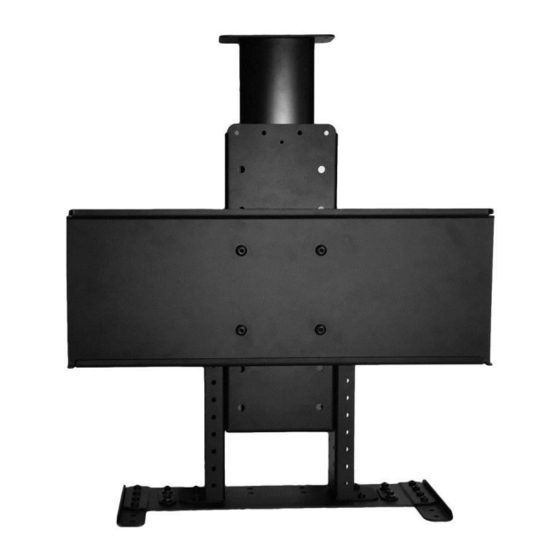
- Page 1 TV Lift System Model L-27i Installation Instructions...
- Page 2 Fax: (480) 951-6879 Revised: 6/23/15 Below is a parts list describing all of the items included with the Model L-27i Lift System. You may also wish to refer to the dimensional diagram shown on Supplemental Page A for minimum installation dimensions (found on page 21).
- Page 3 Cables Motor Cable – Black cable with white, six-pin plugs. Use this cable to connect the Lift Column to the Control Box (using port #1 on the Control Box). Six feet long. Power Cable – Connects Control Box to power outlet. Three feet long. ...
-
Page 4: Safety Information
Nexus 21 disclaims any liability for modifications, improper installations, or installations over the specified weight range. Nexus 21 will not be liable for any damages arising out of the use of, or inability to use, Nexus 21 products. Nexus 21 bears no responsibility for incidental or consequential damages. - Page 5 Types of Controls for Nexus 21 Lift Systems All Nexus 21 Lift Systems come standard with a wireless remote control and receiver. We offer a choice of two different type of remotes: IR and RF (both of which are explained in detail below). Our standard control type is RF, so unless you specifically requested the IR version when you made your purchase, you probably received the RF controls with this Lift System.
-
Page 6: Important Note
The Lift Column is ONLY designed and rated for VERTICAL, INVERTED USE. DO NOT MOUNT THIS LIFT SYSTEM UPSIDE DOWN or SIDEWAYS (HORIZONTALLY, AS IN A LATERAL MOUNT)! Space requirements for the L-27i Lift System are as follows: Depth= TV depth PLUS 5.5”... - Page 7 Assembly and Mounting Instructions – DETAILED STEPS Preparing the Enclosure Box BEFORE BEGINNING, PLEASE READ THE SAFETY NOTICE ON THE FIRST PAGE OF THIS DOCUMENT ¾” The Enclosure Box for the TV and Lift System should be constructed of materials no less than thick.
- Page 8 Assembly and Mounting Instructions – You Are Ready to Start Please perform the following steps, in order: Step 1: Inventory the Parts List. Carefully inspect all items, making sure you have everything shown in the Parts List. Step 2: Seat the “pigtail” cable properly on the top of the Lift Column. Take the Lift Column (Part #1) and find the end with the short black cable (this cable is called the “pigtail”).
- Page 9 Step 3b: Lightly tap the right and left side of the Bayonet Bracket with a rubber mallet to properly seat the bracket. Turn the Lift Column around and check to make sure the Bayonet Bracket is level. Step 4: Place the Base Mount (Part #2) inside of your enclosure against the back wall and the top panel of the enclosure. Make sure to center the Base Mount from left to right inside the enclosure.
- Page 10 Step 6: Attach the Lift Column to the Base Mount. Place the Lift Column (Part #1) with the Bayonet Bracket (Part #3) attached against the back wall of the enclosure. Using the provided small 4mm Allen Wrench drive the (4) 6mm x 40mm FHMS Screws into the top of the lift column.
- Page 11 Step 9a: Attach the Screen Back Plate (Part #6) to the Screen Support Bracket (Part #4). Using (4) 3/8-16 x ¾” BHMS attached the Screen Back Plate to center of the Screen Support Bracket. NOTE: Make sure the bent tabs on the Screen Back Plate are on the top.
- Page 12 Step 11: Attach the Top Support Brackets (Part #9) to the Screen Support Bracket (Part #4) . Using (6) 6mm x 12mm BHMS (3 screws per side) fasten the Top Support Brackets, so the bottom of the Top Support Brackets are a ½” above the opening at the bottom of the enclosure.
- Page 13 Step 13: Mounting the Controls to the Back Panel of the Enclosure: Using (2) #10” x 1 ¾” FHWS attach the Control Box and (2) #8” x ¾” FHWS for the IR or RF Receiver (Depending on which Controls you ordered) to the back panel of the enclosure.
- Page 14 IF YOU HAVE IR CONTROLS, USE THIS DIAGRAM (for RF Controls, see the following page) Once you have connected the controls, test the Lift Column as follows: First, you need to “initialize” the Lift System. If you have already lowered the Lift Column, raise it again, since this step must be performed in the “up”...
- Page 15 IF YOU HAVE RF CONTROLS, USE THIS DIAGRAM (for IR Controls, see the previous page) Once you have connected the controls, test the Lift Column as follows: First, you need to “initialize” the Lift System. If you have already lowered the Lift Column, raise it again, since this step must be performed in the “up”...
- Page 16 Installing the Lid Stabilization Assembly The two Lid Stabilization Assemblies (each consisting of parts #21 - 25) are used to hold the Ceiling Cover Cut-out in proper alignment with ceiling opening. The assemblies are spring loaded so the Ceiling Cut-out will stop level with the ceiling allowing the Lift to travel an additional 1/8 ”–...
- Page 17 Step 14a: Hold your lid piece (your ceiling cut-out piece) up to the Lid Plate (part #5), which you have already installed on the lift. The Lid Plate has 2 holes that are used to attach your lid piece. Mark the position of the holes on your lid piece. Drill two holes ½”...
- Page 18 Step 15b: Place the lid material against the bottom side of the Lid Plate; slide the Threaded Studs through the two holes on the Lid Plate. Slide (2) Lid Stabilization Springs (Part #24) over the Threaded Studs. Step 15c: Add a 1” Fender Washer to the Threaded Studs on top of the spring you previously installed.
- Page 19 Mounting the TV to the Lift Flat/Unobstructed Back Diagram “A” installation procedure: 1) Place the flat screen TV face down on a protected surface. 2) Position the Vertical Mounting Bars equidistant from the bottom and top of the TV, with the slots facing toward the top of the TV.
- Page 20 TV. This will help aid the cables back into the enclosure as the lift fully retracts. Test operate the lift and be sure that all wires are clear of the lift, so they do not get “hung up” when the TV is moving in either direction. Congratulations your L-27i Lift System is now completed!
- Page 21 Supplemental Page A: Dimensional Diagram...
- Page 22 Supplemental Page B: Setting a Height Limit Please follow this procedure if you would like to limit the distance that your TV Lift extends. To set your Travel Limit with IR Controls: If you want the lift system to always go to its full extension, do NOT use the Height Limit Insert. Simply leave it unplugged and the system will always travel to the full extension.
- Page 23 Supplemental Page C: Connect the Lift to Home Control System...
- Page 24 866.500.5438...
Need help?
Do you have a question about the L-27i and is the answer not in the manual?
Questions and answers
How much is the L27i?