Advertisement
Quick Links
Advertisement

Related Manuals for Nexus 21 DL-45b


Summary of Contents for Nexus 21 DL-45b
- Page 1 TV Lift System Model DL-45b Installation Instructions...
-
Page 3: Parts List
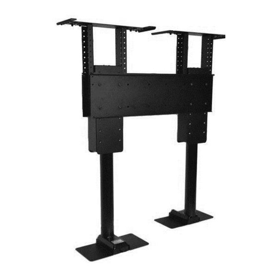
Fax: (480) 951-6879 Revision: 6/07/16 Below is a parts list describing all of the items included with the Model DL-45b Lift System. You may also wish to refer to the diagram shown on “Supplemental Page A” (at the end of this document). - Page 4 Parts List, continued Cables Motor Cable – Black cable with white, six-pin plugs. Use this cable to connect the Lift Column to the Control Box (using slot #1 & #2 on the Control Box). Three feet long. Power Cable – Connects Control Box to power outlet. Three feet long. ...
-
Page 6: Safety Information
Nexus 21 disclaims any liability for modifications, improper installations, or installations over the specified weight range. Nexus 21 will not be liable for any damages arising out of the use of, or inability to use, Nexus 21 products. Nexus 21 bears no responsibility for incidental or consequential damages. - Page 7 Types of Controls for Nexus 21 Lift Systems All Nexus 21 Lift Systems come standard with a wireless remote control and receiver. We offer a choice of two different type of remotes: IR and RF (both of which are explained in detail below). Our standard control type is RF, so unless you specifically requested the IR version when you made your purchase, you probably received the RF controls with this Lift System.
-
Page 8: Safety Notice
MOUNT THIS LIFT SYSTEM UPSIDE DOWN or SIDEWAYS (HORIZONTALLY, AS IN A LATERAL MOUNT)! TIP: Inverted (drop down) lift systems are available from Nexus 21. Contact Customer Service at (866) 500-5438. Space requirements for the DL-45B Lift System are as follows: Depth = TV Depth x 2 + 10”, or 16”... - Page 9 Step 1: Inventory the Parts List. Carefully inspect all items, making sure you have everything in the Parts List on page 1. Be sure to open the Nexus 21 TV Mount carton that includes parts #5 and #6. Step 2: Attach four Foot Plates to both Lift Columns. Using the small allen wrench provided, attach two Foot Plates to each lift column using eight (8) 6mm x 16mm BHMS, four (4) per lift column.
- Page 10 Step 4: Attach the Top Support Brackets to the Screen Support Brackets. Measure the interior height of the cabinet, from the base of the cabinet to the bottom side of the lid opening. Use this measurement to figure out exactly what set of holes to use when attaching the Top Support Brackets. The Top Support Brackets should sit ½”...
- Page 11 Step 6: Attach the Screen Back Plates to the Screen Support Brackets. Using sixteen (16) 3/8” x 16mm BHMS Screws (eight screws per Screen Back Plate) fasten the Screen Back Plates to both of the Screen Support Brackets. Make sure to rotate one lift column, so both lift columns face the opposite direction before you attach the plates.
- Page 12 Step 8: Mount the Foot Plates to the base of the cabinet. Using Twelve (12) #10 x ¾” THWS Screws (six screws per Foot Plate) fasten both Foot Plates to the base of the cabinet. NOTE: You may need to twist or rotate the lift columns in order to square the Foot Plates with the cabinet walls.
- Page 13 IF YOU HAVE IR CONTROLS, USE THIS DIAGRAM (for RF Controls, see the following page) DL-45b Wiring Diagram with IR Controls Once you have connected the controls, test the Lift Column as follows: First, you need to “initialize” the Lift System. If you have already raised the Lift Column, lower it again, since this step must be performed in the “down”...
- Page 14 IF YOU HAVE RF CONTROLS, USE THIS DIAGRAM (for IR Controls, see the previous page) DL-45b Wiring Diagram with RF Controls Once you have connected the controls, test the Lift Column as follows: First, you need to “initialize” the Lift System. If you have already raised the Lift Column, lower it again, since this step must be performed in the “down”...
- Page 15 Installing the Tapered Pins in the Floating Lid What Are the Tapered Pins, and Why Use Them? The two 1½” x ¼” Steel Threaded Tapered Pins are used IN PLACE OF SCREWS to hold your cabinet top (lid) in place on the Lift System Top Plate (Part #8). The Tapered Pins will keep your lid firmly in place, but will also allow it to separate from the lift system if anything (like a finger) gets in the way when the TV lowers.
- Page 16 How to Install the Tapered Pins: You will be screwing the Tapered Pins into the UNDERSIDE of your cabinet lid, and they will hang down and drop into the two holes in the Top Plate (Part #7). Step 11: Before installing the Tapered Pins, position the Cabinet Lid. With the Lift System in the fully DOWN position, make sure the Top Plate is within ½”...
- Page 17 Test operate the Lift and be sure that all wires are clear of the Lift so they do not get “hung up” when the TV’s are moving either up or down. Congratulations your DL-45b Lift System is now completed!
- Page 18 Mounting the TV to the Lift Flat/Unobstructed Back Diagram “A” installation procedure: 1) Place the flat screen TV face down on a protected surface. 2) Position the Vertical Mounting Bars equidistant from the bottom and top of the TV, with the slots facing toward the top of the TV.
- Page 19 Supplemental Page A: Dimensional Diagram...
- Page 20 Supplemental Page B: Setting a Height Limit Please follow this procedure if you would like to limit the distance that your TV Lift extends. To set your Travel Limit with IR Controls: If you want the lift system to always go to its full extension, do NOT use the Height Limit Insert. Simply leave it unplugged and the system will always travel to the full extension.
- Page 21 Supplemental Page C: Connect the Lift to Home Control System...
- Page 24 866.500.5438...
Need help?
Do you have a question about the DL-45b and is the answer not in the manual?
Questions and answers