Bloomfield 1012 Owner's Manual
E. b. c. electronic brew control decanter coffee brewers
Hide thumbs
Also See for 1012:
- Owner's manual (34 pages) ,
- Brochure (34 pages) ,
- Specifications (2 pages)
Table of Contents
Advertisement
Quick Links
Wunder-Bar
2060 Cessna Drive, Suite 100
Vacaville, CA 95688 U.S.A
Phone: (707) 448-5151
Fax (707) 448-1521
www.wunderbar.com
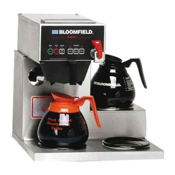
Models 1012 Brewer
with optional
8900-Series Glass Decanters
75844
p/n 2m-
Rev.I
Model 1072 Brewer
with optional
8900-Series Glass Decanters
OWNERS MANUAL
for
E. B. C.™
Electronic
Brew
Control ™
DECANTER
COFFEE BREWERS
MODELS
1012
1040
1072
Includes:
Installation
Use & Care
Servicing Instructions
E.B.C.™ brewers are protected under
U. S. Patent # 5,704,275
Other U. S. and Canadian patents pending.
13
M641
641
0319
Advertisement
Table of Contents

Subscribe to Our Youtube Channel
Related Manuals for Bloomfield 1012


Summary of Contents for Bloomfield 1012
- Page 1 Vacaville, CA 95688 U.S.A Phone: (707) 448-5151 Fax (707) 448-1521 www.wunderbar.com OWNERS MANUAL E. B. C.™ Electronic Brew Control ™ DECANTER Models 1012 Brewer with optional COFFEE BREWERS 8900-Series Glass Decanters MODELS 1012 1040 1072 Includes: Installation Use & Care...
- Page 2 WARRANTY STATEMENT All electrical equipment manufactured by BLOOMFIELD is removed or unauthorized service personnel perform service. warranted against defects in materials and workmanship for a period of (1 year labor, two year parts) from the date upon the limitations in this warranty. Seller’s obligation under...
-
Page 3: Specifications
SPECIFICATIONS MODEL STYLE VOLTS WATTS AMPS 1PH POWER SUPPLY CORD 120V 1800 NEMA 5-15P 220/240V E.B.C. SERIES 1012 3W IN-LINE 230V 2100 CEE7/7 BS 1363A 120V 14.2 NEMA 5-15P 1040 2W IN-LINE 1700 BS 1363A 7.39... - Page 4 FEATURES AND OPERATING CONTROLS FEATURES AND OPERATING CONTROLS Fig. 1 Features & Operating Controls Fig. 1 Features & Operating Controls...
-
Page 5: Precautions And General Information
PRECAUTIONS AND GENERAL INFORMATION WARNING: ELECTRIC SHOCK HAZARD service personnel. Do not open any access panels which require the use of tools. Failure to heed this warning can result in electrical shock. WARNING: INJURY HAZARD applicable electrical and plumbing codes. Failure could result in property damage and personal injury. -
Page 6: Installation Instructions
INSTALLATION INSTRUCTIONS READ THIS CAREFULLY BEFORE STARTING THE INSTALLATION IMPORTANT: Unpack the unit. Inspect all components for completeness and To enable the installer to make condition. Ensure that all packing materials have been removed a quality installation and to from the unit. minimize installation time, the Verify that the Spray Head Gasket (#33) and Spray Disk (#34) following suggestions and tests... - Page 7 Models 1012, 1040 & 1072 (US only) are equipped with a cord and plug. They require a 115 - 125 volt 15 amp circuit (50/60 Hz, 2 wire plus ground, with NEMA 5-15R or 5-20R Receptacle).
-
Page 8: Operation
OPERATION IL2203 Fig. 4 Brewer Operation Diagram IMPORTANT: START-UP Tank must be full of For initial start-up, or if the brewer has not been used for an water before connecting extended period of time: brewer to electrical power. • Be sure spray disk and brew gasket are properly installed in the Heating elements will be brew head. -
Page 9: Water Heater
OPERATION (continued) OPERATION (continued) WATER HEATER Water temperature is sensed by an electronic water temperature probe inserted into the water tank. This temperature signal is fed to the controller. The setpoint temperature is adjustable. The controller sends a command signal to the power board based upon a comparison between the setpoint temperature and actual temperature. -
Page 10: Electronic Features
OPERATION (continued) IMPORTANT: ELECTRONIC FEATURES DO NOT energize this Energizing the Brewer brewer until the water times and four beeps will sound. The unit will be elements. See page 6. once. The POWER indicator will remain . If the water temperature is more than 10ºF below the setpoint, the HEAT indicator will glow until water temperature reaches setpoint. - Page 11 OPERATION (continued) Quality Timer Quality Timer is normally set for 30 minutes. It can Coffee looses its freshness as it sits on a warmer. The Quality Timer be set for 20 minutes by that the coffee is nearing the end of its useful life. moving a jumper on the controller.
-
Page 12: Brewing Coffee
BREWING COFFEE CAUTION: PREPARATION BURN HAZARD Place one (1) genuine Exposed surfaces of the brew chamber. brewer, brew chamber and PAPER decanter may be HOT to Add a pre-measured amount FILTER the touch, and can cause of fresh coffee grounds. serious burns. -
Page 13: Cleaning Instructions
CLEANING INSTRUCTIONS PROCEDURE: Clean Coffee Brewer CAUTION: BURN HAZARD PRECAUTIONS: Disconnect brewer from electric power. Allow brewer to cool. Brewing and serving temperatures of coffee are FREQUENCY: Daily extremely hot. Hot coffee will cause TOOLS: Mild Detergent, Clean Soft Cloth or Sponge serious skin burns. -
Page 14: Troubleshooting Suggestions
TROUBLESHOOTING SUGGESTIONS SYMPTOM POSSIBLE CAUSE SUGGESTED REMEDY Brewer unplugged or circuit breaker Check power supply cord, tripped Check / reset circuit breaker Temperature adjusted too low or set Turn on and set for desired to off temperature. See page 15 Water won’t heat (NOTE: Models 1016 &... -
Page 15: Error Detection
ERROR DETECTION This brewer is designed to perform a continuous internal CAUTION: SHOCK HAZARD “off”, and most keypad functions are disabled. Live electrical circuits may be exposed while performing these procedures. Anytime a temperature in excess of 214ºF is detected. These procedures are to Temperature does not change by at least 2ºF within 4 minutes of tank heater being energized (HEAT light on). -
Page 16: Servicing Instructions
SERVICING INSTRUCTIONS ACCESS PANELS CAUTION: SHOCK HAZARD TOP PANEL: Remove top panel to access hot water tank, thermo probe, Opening access panels or heating elements, brew circuit tubing, faucet valve and piping. removing warmer plates on this brew may expose uninsulated Top panel is held by two screws at the rear and a retaining lip at electrical components. -
Page 17: Temperature Adjustment
SERVICING INSTRUCTIONS (continued) TEMPERATURE ADJUSTMENT CAUTION: Unplug power cord or turn circuit breaker OFF. Remove top SHOCK HAZARD panel. Remove button plug from front panel. Pull vent tube out of tank lid and insert a thermometer of known These procedures involve accuracy in vent hole. - Page 18 SERVICING INSTRUCTIONS (continued) IMPORTANT: Water pressure BREW TIME ADJUSTMENT must be between 20 p.s.i and The amount of water dispensed automatically during a brew cycle is controlled by the SOLENOID TIME dial of the controller. water pressure exceeds this Place empty decanter under brew chamber. Press BREW value, or if water pressure button.
-
Page 19: Replace Solenoid
SERVICING INSTRUCTIONS (continued) REPLACE SOLENOID Unplug power cord. Turn OFF and disconnect water supply from Remove front panel. Remove two screws holding access door in SOLENOID SCREEN cap to release solenoid from door. WASHER INLET Remove wiring from solenoid. FITTING IL1693a Large end of wrench 86660 can be used to hold solenoid inlet Fill... - Page 20 SERVICING INSTRUCTIONS (continued) IMPORTANT: When replacing REPLACE HOT WATER FAUCET COIL (Symptom: Brewer drips continuously from brew head, except water faucet coil, also replace when faucet valve is turned OFF.) seal gaskets. Remove tank lid assembly per above. Remove two hex nuts hot water coil to cover. Pull coil from mounting holes.
- Page 21 SERVICING INSTRUCTIONS (continued) SET CONTROLLER JUMPERS Placing the jumper across Q1 sets Quality Time at 20 Minutes. Placing the jumper across Q2 sets Quality Time at 30 Minutes. Removing jumpers from both Q1 or Q2 disables Quality Timer. Placing the jumper across V1 sets Valve Time Range to 60 - 180 seconds.
- Page 22 SERVICING INSTRUCTIONS (continued) CAUTION: PROCEDURE: Delime the Water Tank CHEMICAL BURN HAZARD PRECAUTIONS: Disconnect brewer from electric power. Allow brewer to cool. Deliming chemicals are caustic. Wear appropriate protective gloves and goggles during FREQUENCY: As required (Brewer slow to heat) this procedure.
-
Page 24: Exploded View And Parts List
EXPLODED VIEW & PARTS LIST CABINET COMPONENTS - IN-LINE BREWERS CABINET COMPONENTS - IN-LINE BREWERS... - Page 25 EXPLODED VIEW & PARTS LIST (continued) Cabinet Components for Models: 1012, 1040 ITEM PART NO. DESCRIPTION USED ON 2D-70090 Warmer Plate Black, 1/4-28 Stud 1012, 1040 Units Made in USA 2D-Z15630 Plate Cover Warmer, 1/4-20 Stud 1012, 1040 Units Made in China...
- Page 26 EXPLODED VIEW & PARTS LIST (continued) CABINET COMPONENTS - LO-PROFILE BREWERS...
- Page 27 EXPLODED VIEW & PARTS LIST (continued) Cabinet Components for Models: 1072 ITEM PART NO. DESCRIPTION USED ON 1072, Units Made in USA 2D-70090 Warmer Plate Black, 1/4-28 Stud 2D-Z15630 Plate Cover Warmer, 1/4-20 Stud 1072, Units Made in China 2I-70139 Spray Head Gasket 1072 A6-72727...
- Page 28 EXPLODED VIEW & PARTS LIST (continued) HOT WATER TANK ASSEMBLY IL2212 ITEM PART NO. DESCRIPTION 2C-70134 Hold Down Strap 2C-70133 Nut, 8-32 SS Acorn Screw, 1/4-20 X 1-1/4 SS Cap Head Nut, 1/4-20 SS 2J-73644 Temperature Probe 2I--73731 Seal Washer 2I-70147 Tank Cover Gasket 2I-70152...
-
Page 29: Electrical Components
Solenoid Bypass 230V 2E-74570 Solenoid Valve, 240V 220/240V 2J-73644 Temperature Probe 2T-47499 Hi-Limit Thermostat 1012, 1040, 1072 2T-72956 Thermal Hi-Limit Manual 230V 2N-70143UL Tank Heating Element 120V / 1500W 1012, 1040, 1072 2N-70167UL Tank Heating Element 120V / 1200W 1072-120C... - Page 30 EXPLODED VIEW & PARTS LIST (continued) INTERNAL PLUMBING COMPONENTS IL2214 ITEM PART NO. DESCRIPTION USED ON 2V-70104 Faucet Outlet Tube Assembly 2V-70111 Formed Inlet Tube Assembly A6-70118 Needle Valve (Faucet Shut-Off) Assy 2J-75681 Inlet Tube Assembly Braided 2K-70096 Elbow 2V-70131 Tube Outlet Water 4-3/4 SS 2K-70130 Sprayer Elbow...
-
Page 31: Wiring Diagram
WIRING DIAGRAM... - Page 32 WIRING DIAGRAM p/n 75373...
- Page 33 WIRING DIAGRAM (continued) HEATING ELEMENT 120V: 1500W 120C: 1200W 120V 1800 120C 1500 p/n 2M-75361...
- Page 34 TEMPERATURE ELEMENT WARMER PROBE ELEMENT TANK C1-2 ELEMENT LINE NEUTRAL GROUND POWER SWITCH WARMING ELEMENTS ONLY ON MODELS 1012, 1040, AND 1072 POWER SWITCH ONLY ON MODELS 1086 AND 1088 2M-Z16607 230V MODELS: 1012, 1040, 1072, 1080, 1082, 1086, 1088...
- Page 35 NOTES...
Need help?
Do you have a question about the 1012 and is the answer not in the manual?
Questions and answers