Advertisement
Quick Links
10 Sunnen Drive
St. Louis, MO 63143
telephone: 314-678-6336
fax: 314-781-2714
www.bloomfieldworldwide.com
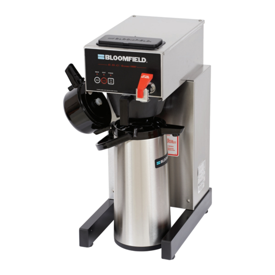
Model 1082 Brewer
with optional
7752 Airpot
75872
p/n 2M-
Rev. H
OWNERS MANUAL
for
E. B. C.™
Electronic
Brew
Control ™
AIRPOT AND
THERMAL SERVER
COFFEE BREWERS
MODELS
1080
1082
1082XL
1086
1088
Includes:
Installation
Use & Care
Servicing Instructions
E.B.C.™ brewers are protected under
U. S. Patent # 5, 704,275
Other U. S. and Canadian patents pending.
642
12
M642
0224
Advertisement

Related Manuals for Bloomfield E. B. C. Electronic Brew Control


Summary of Contents for Bloomfield E. B. C. Electronic Brew Control
- Page 1 10 Sunnen Drive St. Louis, MO 63143 telephone: 314-678-6336 fax: 314-781-2714 www.bloomfieldworldwide.com OWNERS MANUAL E. B. C.™ Electronic Brew Control ™ AIRPOT AND THERMAL SERVER COFFEE BREWERS MODELS 1080 1082 1082XL 1086 1088 Includes: Installation Use & Care Servicing Instructions E.B.C.™...
- Page 2 WARRANTY STATEMENT All electrical equipment manufactured by BLOOMFIELD is The prices charged by Bloomfield for its products are based warranted against defects in materials and workmanship upon the limitations in this warranty. Seller’s obligation under for a period of (1 year labor, two year parts) from the date...
- Page 3 3 WIRE Requires 3 wire + gnd cord not supplied 1088 AIRPOT 115/230 3500 15.2 3 WIRE Meets Canadian standards APPLICABILITY This manual applies to the following Bloomfield E. B. C. products: ® 1080CA 1080 1082ACA 1082CA 1082 1082XLCA 1082XL 1086...
- Page 4 FEATURES AND OPERATING CONTROLS IL1726 Fig. 1 Features & Operating Controls...
- Page 5 PRECAUTIONS AND GENERAL INFORMATION WARNING: ELECTRIC SHOCK HAZARD All servicing requiring access to non-insulated components must be performed by qualified service personnel. Do not open any access panels which require the use of tools. Failure to heed this warning can result in electrical shock. WARNING: INJURY HAZARD All installation procedures must be performed by qualified personnel with full knowledge of all...
- Page 6 Bloomfield recommends 1/4” copper tubing for installation of less than 25 feet and 3/8” for more than 25 feet from a 1/2”...
- Page 7 INSTALLATION INSTRUCTIONS (continued) NSF requires that the brewer be able to be moved for cleaning NOTE: This equipment must underneath. A flex line or loops of copper tubing will satisfy this be installed to comply with requirement. See Figure 2 below. applicable federal, state and local plumbing codes and ordinances.
- Page 8 OPERATION Fig. 4 Brewer Operation Diagram IMPORTANT: START-UP Tank must be full of For initial start-up, or if the brewer has not been used for an water before connecting extended period of time: brewer to electrical power. • Be sure spray disk and brew gasket are properly installed in the Heating elements will be brew head.
-
Page 9: Water Heater
OPERATION (continued) WATER HEATER Water temperature is sensed by an electronic water temperature probe inserted into the water tank. This temperature signal is fed to the controller. The setpoint temperature is adjustable. The controller sends a command signal to the power board based upon a comparison between the setpoint temperature and actual temperature. - Page 10 OPERATION (continued) IMPORTANT: ELECTRONIC FEATURES DO NOT energize this brewer until the water Energizing the Brewer tank has been filled. Dry When electric power is applied to the unit, all the lights will flash four firing will damage heating times and four beeps will sound. The unit will be elements.
- Page 11 OPERATION (continued) Quality Timer is normally Quality Timer set for 30 minutes. It can Coffee looses its freshness as it sits on a warmer. The Quality Timer flashes the warmer lights 30 minutes after the last brew to remind you be set for 20 minutes by that the coffee is nearing the end of its useful life.
- Page 12 BREWING COFFEE CAUTION: PREPARATION Place one (1) genuine Bloomfield BURN HAZARD PAPER paper filter in the brew chamber. FILTER Exposed surfaces of the Add a pre-measured amount of brewer, brew chamber and fresh coffee grounds. BREW airpot or server may be...
- Page 13 CLEANING INSTRUCTIONS CAUTION: PROCEDURE: Clean Coffee Brewer BURN HAZARD PRECAUTIONS: Disconnect brewer from electric power. Brewing and serving Allow brewer to cool. temperatures of coffee are extremely hot. FREQUENCY: Daily Hot coffee will cause serious skin burns. TOOLS: Mild Detergent, Clean Soft Cloth or Sponge Bristle Brush.
- Page 14 Coffee level too high or low Timer out of adjustment Adjust controller. See page 16 Too many filter papers or wrong filter Use one (1) genuine Bloomfield paper filter per brew Brew chamber overflows Brew chamber dispense hole plugged...
- Page 15 ERROR DETECTION This brewer is designed to perform a continuous internal WARNING: diagnosis, and to signal faults by flashing all the lights. In fault SHOCK HAZARD mode, warmers, heating element and water fill solenoid are turned “off”, and most keypad functions are disabled. Live electrical circuits may be exposed while performing Error detection (all lights flashing) will occur under two conditions:...
- Page 16 SERVICING INSTRUCTIONS ACCESS PANELS WARNING: SHOCK HAZARD TOP PANEL: Remove top panel to access hot water tank, thermo probe, Opening access panels or heating elements, brew circuit tubing, faucet valve and piping. removing warmer plates on this brew may expose uninsulated Top panel is held by two screws at the rear and a retaining lip at electrical components.
- Page 17 SERVICING INSTRUCTIONS (continued) TEMPERATURE ADJUSTMENT WARNING: Unplug power cord or turn circuit breaker OFF. Remove top SHOCK HAZARD panel. Remove button plug from front panel. These procedures involve exposed electrical circuits. These procedures are to be performed by qualified technical personnel only. Fig.
- Page 18 SERVICING INSTRUCTIONS (continued) IMPORTANT: Water pressure BREW TIME ADJUSTMENT must be between 20 p.s.i and The amount of water dispensed automatically during a brew cycle 90 p.s.i. flowing pressure. If is controlled by the SOLENOID TIME dial of the controller. water pressure exceeds this Place empty decanter under brew chamber.
- Page 19 SERVICING INSTRUCTIONS (continued) REPLACE SOLENOID Unplug power cord. Turn OFF and disconnect water supply from brewer inlet fitting. Remove front panel. Remove two screws holding access door in place. Remove access door and solenoid. Unscrew inlet fitting cap to release solenoid from door. Remove wiring from solenoid.
- Page 20 SERVICING INSTRUCTIONS (continued) IMPORTANT: When replacing REPLACE HOT WATER FAUCET COIL (Symptom: Brewer drips continuously from brew head, except water faucet coil, also replace when faucet valve is turned OFF.) seal gaskets. Remove tank lid assembly per above. Remove two hex nuts hot water coil to cover. Pull coil from mounting holes.
- Page 21 SERVICING INSTRUCTIONS (continued) SET CONTROLLER JUMPERS Placing the jumper across Q1 sets Quality Time at 20 Minutes. Placing the jumper across Q2 sets Quality Time at 30 Minutes. Removing jumpers from both Q1 or Q2 disables Quality Timer. Placing the jumper across V1 sets Valve Time Range to 60 - 180 seconds.
- Page 22 Should deliming hoses 7. Set the tank back into the brewer. Reassemble the tank lid become necessary, Bloomfield to the water tank. Make sure the gasket is properly in place, recommends replacing the and then reinstall the hold-down strap.
- Page 23 NOTES:...
- Page 24 EXPLODED VIEW & PARTS LIST HOT WATER TANK ASSEMBLY ITEM PART NO. DESCRIPTION USED ON 2C-70134 Hold Down Strap 2C-70133 Nut, 8-32 SS Acorn 2C-40366 Screw, 1/4-20 X 1-1/4 SS Cap Head DD-49401 Nut, 1/4-20 SS 2J-73644 Temperature Probe 2I-73731 Seal Washer 2I-70147 Tank Cover Gasket...
- Page 25 EXPLODED VIEW & PARTS LIST (continued) ELECTRICAL COMPONENTS ITEM PART NO. DESCRIPTION USED ON 2E-72936 Switch, Rocker 125/250V 1086, 1088 2C-74859 Keypad 2E-70353 Cord & Cap Assembly 1080, 1082 2E-70709 Terminal Strip 1086, 1088 2K-70215 Strain Relief 1080, 1082 2V-70124 Valve-Sol, 120V Metal All .75GPM Solenoid Bypass, 120V, .30GPM...
- Page 26 EXPLODED VIEW & PARTS LIST (continued) INTERNAL PLUMBING COMPONENTS ITEM PART NO. DESCRIPTION USED ON 2V-70104 Faucet Outlet Tube Assembly 2V-70111 Formed Inlet Tube Assembly A6-70118 Needle Valve (Faucet Shut-Off) Assy 2J-75681 Inlet Tube Assembly Braided 2K-70096 Elbow 2V-70131 Tube Outlet Water 4-3/4 SS 2K-70130 Sprayer Elbow 2C-72680...
- Page 27 Front Panel w/Mounting Provision for Bracket 1082XL Mounting, Power Board Access Door, Solenoid 2F-76666 Pour-Over Assy WS-8542-6 Top Panel 2D-70095 Basin Pan Basin Body, Welded Assy WS-8942-6 Brew Chamber, Brown 2D-70114 Brew Chamber, Stainless WS-POF Bloomfield Paper Filter (pk 1000)
- Page 28 WIRING DIAGRAM E.B.C.ô BREWER MODEL VOLTS WATTS AMPS 1080 1800 1080CA 1500 1082 1800 1082CA 1500 CONTROL BOARD TEMPERATURE PROBE POWER BOARD NEUTRAL IN VALVE B WHITE HEATER B LIMIT INLET BLACK VALVE A BLACK VALVE .5 GPM LINE IN HEATER A HEATING ELEMENT...
- Page 29 WIRING DIAGRAM (continued) E.B.C.™ BREWER MODEL VOLTS WATTS AMPS 1086 115/230 3500 1088 115/230 3500 CONTROL BOARD TEMPERATURE PROBE POWER BOARD WHITE 12 ga NEUTRAL IN WHITE VALVE B HEATER B LIMIT INLET BLACK BLACK 12 ga VALVE A VALVE BLACK 12 ga .5 GPM LINE IN...
- Page 30 NOTES...
- Page 31 NOTES...
- Page 32 10 Sunnen Drive, St. Louis, MO 63143 telephone: 314-678-6336 fax: 314-781-2714 www.bloomfieldworldwide.com...
Need help?
Do you have a question about the E. B. C. Electronic Brew Control and is the answer not in the manual?
Questions and answers