
Related Manuals for MR CEDASPE VP Series


Summary of Contents for MR CEDASPE VP Series
- Page 1 THE POWER BEHIND POWER. Operating instructions Pressure relief device. CEDASPE® VP series 10679401/00 EN...
- Page 2 Generally the information provided and agreements made when processing the individual quotations and orders are binding. The product is delivered in accordance with MR's technical specifications, which are based on information provided by the customer. The customer has a duty of care to ensure the compatibility of the specified product with the customer's planned scope of application.
-
Page 3: Table Of Contents
Table of contents Introduction .............. 5 Manufacturer ................... 5 Safekeeping ..................... 5 Notation conventions................ 5 1.3.1 Hazard communication system............. 5 1.3.2 Information system................. 7 1.3.3 Instruction system .................. 7 1.3.4 Typographic conventions............... 8 Security ................ 9 Intended use .................... 9 Fundamental safety instructions............ 10 Personnel qualification ................. 12 Personal protective equipment ............ 13 Product description............ - Page 4 Electrical connection................ 36 5.4.1 Cable recommendation................ 37 5.4.2 Connection via connection box (Crouzet version)...... 37 5.4.3 Connection via limit-value switch (Telemecanique version) .... 39 Commissioning ............ 40 Filling with oil and performing the venting test ........ 40 Leak test.................... 41 Removing the protective panel on the signal pin (VP150-QT and VP150-ST) .................... 41 Checking the function of the micro-switches ........
-
Page 5: Introduction
1 Introduction This technical file contains detailed descriptions on the safe and proper in- stallation, connection, commissioning and monitoring of the product. This technical document is intended solely for specially trained and autho- rized personnel. 1.1 Manufacturer CEDASPE S.r.l. Via Colombara 1 20098 S. - Page 6 1.3.1.1 Warning relating to section Warnings relating to sections refer to entire chapters or sections, sub-sec- tions or several paragraphs within this technical document. Warnings relating to sections have the following format: WARNING Type of danger! Source of the danger and its consequences. Action Action 1.3.1.2 Embedded warning information...
-
Page 7: Information System
1.3.2 Information system Information is designed to simplify and improve understanding of particular procedures. In this technical file it is laid out as follows: Important information. 1.3.3 Instruction system This technical file contains single-step and multi-step instructions. Single-step instructions Instructions which consist of only a single process step are structured as fol- lows: Aim of action Requirements (optional). -
Page 8: Typographic Conventions
1.3.4 Typographic conventions Typographic convention Purpose Example UPPERCASE Operating controls, ON/OFF switches [Brackets] PC keyboard [Ctrl] + [Alt] Bold Software operating controls Press Continue button …>…>… Menu paths Parameter > Control param- eter Italics System messages, error Function monitoring alarm messages, signals triggered [►... -
Page 9: Security
2 Security Read this technical file through carefully to familiarize yourself with the prod- uct. This technical file is a part of the product. – Read and observe the safety instructions provided in this chapter in partic- ular. – Observe the warnings in this technical file to avoid function-related dan- gers. -
Page 10: Fundamental Safety Instructions
2.2 Fundamental safety instructions To prevent accidents, malfunctions and damage as well as unacceptable ad- verse effects on the environment, those responsible for transport, installa- tion, operation, maintenance and disposal of the product or parts of the product must ensure the following: Personal protective equipment Loosely worn or unsuitable clothing increases the danger of becoming trapped or caught up in rotating parts and the danger of getting caught on... - Page 11 Safety markings Warning signs and safety information plates are safety markings on the prod- uct. They are an important aspect of the safety concept. Safety markings are depicted and described in the chapter "Product description". – Observe all safety markings on the product. –...
-
Page 12: Personnel Qualification
2.3 Personnel qualification The person responsible for assembly, commissioning, operation and inspec- tion must ensure that personnel are sufficiently qualified. Electrically skilled person The electrically skilled person has a technical qualification and therefore has the required knowledge and experience, and is also conversant with the ap- plicable standards and regulations. -
Page 13: Personal Protective Equipment
CEDASPE S.r.l Via Colombara 1 20098 S. Giuliano Milanese (MI) Italy Tel.: +39 029 820 4411 Internet: www.reinhausen.com 2.4 Personal protective equipment Personal protective equipment must be worn during work to minimize risks to health. – Always wear the personal protective equipment required for the job at hand. -
Page 14: Product Description
3 Product description 3.1 Scope of delivery The following items are included in the scope of delivery: – Pressure relief device – O-ring gasket for assembly Optional – O-ring gasket for connection to the oil escape opening 3.2 Function description The pressure relief device with the device flange is mounted tightly on the top or on the side of transformer tank or on the on-load tap-changer. -
Page 15: Design/Versions
3.3 Design/versions The pressure relief device is available in various versions, optionally with mi- cro-switches or limit-value switches. The switches are available as Crouzet versions (type K) or as Telemecanique versions (type C). The red signal pin in- dicates that the device has tripped. In addition to the current product name, the different versions of the pres- sure relief device can also be ordered under the historical product name. - Page 16 Current product name Historical product name Product description VP80-QT VQT-2 80 Mounting via 4-hole flange Protective cover with inte- grated terminal box and square 4-hole connection for pipe (Ø 70 mm) for di- rected oil flow VP150-QT VQT-2 150 Mounting via 6-hole flange Protective cover with inte- grated terminal box and square 4-hole flange con-...
-
Page 17: Vp50 Pressure Relief Device
3.3.1 VP50 pressure relief device Figure 1: Device version VP50 design 1 Signal pin 2 Counter bearing for spring assembly 3 Splash guard (optional) 4 Vent screw 5 Device flange 6 Spring assembly 7 Valve plate 8 O-ring gasket 9 Micro-switch (optional) 10 Terminal box 10679401/00 EN Product description 17... -
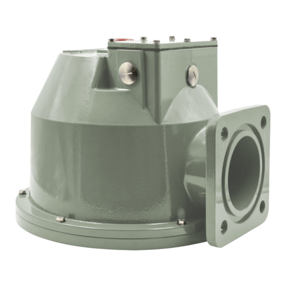
Page 18: Vp80, Vs100 And Vp150 Pressure Relief Device
3.3.2 VP80, VS100 and VP150 pressure relief device Figure 2: Device versions VP80, VS100 and VP150 design 1 Signal pin 2 Counter bearing for spring assembly 3 Splash guard (optional) 4 Terminal box 5 Lever for manual resetting 6 Valve plate 7 O-ring gasket 8 Device flange 9 Vent screw... -
Page 19: Vp80-Qt Pressure Relief Device
3.3.3 VP80-QT pressure relief device Figure 3: Device version VP80-QT design 1 Signal pin 2 Protective cover with connection for pipe for directed oil flow 3 Counter bearing for spring assembly 4 Vent screw 5 O-ring gasket for connecting the 6 O-ring gasket pipe for directed oil flow 7 Valve plate 8 Spring assembly... -
Page 20: Vp150-Qt And Vp150-St Pressure Relief Device
3.3.4 VP150-QT and VP150-ST pressure relief device Figure 4: Device versions VP150-QT and VP150-ST design 1 Signal pin 2 Counter bearing for spring assembly 3 Spring assembly 4 Vent screw 5 Valve plate 6 O-ring gaskets, flange and protec- tive cover 7 Device flange 8 O-ring gasket for connecting the pipe for directed oil flow... -
Page 21: Safety Markings And Nameplate
3.4 Safety markings and nameplate The nameplate is on the device upper side. Figure 5: Nameplate (examples) 1 VP80-QT 2 VP80 10679401/00 EN Product description 21... - Page 22 Figure 6: Nameplates and safety marking (device versions VP150-QT and VP150-ST) 1 Nameplates 2 Safety marking Malfunction! Refer to the Commis- sioning chapter 22 Product description 10679401/00 EN...
-
Page 23: Packaging, Transport And Storage
4 Packaging, transport and storage 4.1 Purpose The packaging is designed to protect the packaged product during transport, loading, unloading and during periods of storage in such a way that no detri- mental changes occur. The packaging must protect the goods against per- mitted transport stresses such as vibration and knocks. -
Page 24: Transportation, Receipt And Handling Of Shipments
4.4 Transportation, receipt and handling of shipments In addition to vibrations, jolts must also be expected during transportation. In order to prevent possible damage, avoid dropping, tipping, knocking over and colliding with the product. If the packaging tips over or falls, damage is to be expected regardless of the weight. -
Page 25: Storage Of Shipments
Hidden damage When damage is not determined until unpacking after receipt of the ship- ment (hidden damage), proceed as follows: – Make the party responsible for the damage liable as soon as possible by telephone and in writing, and prepare a damage report. –... -
Page 26: Mounting
5 Mounting This chapter describes how to correctly mount and connect the device. The pressure relief device is mounted on a device flange on the transformer or on-load tap-changer. Note the connection diagrams provided. DANGER Electric shock! Risk of fatal injury due to electrical voltage. Always observe the following safety regulations when working in or on electrical equipment. - Page 27 CAUTION Risk of injury and damage to property! Escaping hot oil and gas can lead to injuries and damage to the device. Direct escaping hot oil and gas away from people and critical transformer parts. The pressure relief device can be mounted horizontally or vertically, as close as possible to potential error sources.
-
Page 28: Checking The Pipe Flanges
5.1 Checking the pipe flanges The pipe flanges must be flush and clean to allow the device to be positioned with the least possible stress. NOTICE! A residual distance between the flanges caused by a deviation in evenness can cause damage to the flanges.Even slight unevenness can cause the flange of the device to be curved too much, leading to cracks in the flange caused by the resulting transverse stress. -
Page 29: Mounting Device Versions Vp50, Vp80, Vs100 And Vp150
5.2 Mounting device versions VP50, VP80, VS100 and VP150 You must first remove the splash guard to mount the device. After mount- ing, reattach the splash guard to the device. Removing the splash guard 1. Unscrew and remove the fixing screws on the splash guard. Figure 9: Unscrewing the splash guard fixing screws 1 VP50: 6 x fixing screws M4 2 VP80, VS100, VP150: 4 x fixing... - Page 30 Mounting the device Refer to the Drawings chapter for dimensions and connection data. 1. Insert the o-ring gasket included in the delivery underneath the device in the groove intended for this. NOTICE! Malfunction! An incorrectly seated o-ring gasket can result in leaks. When mounting, ensure that the o-ring gasket is seated correctly in the groove intended for this.
- Page 31 NOTICE! Damage to the holes due to a tightening torque that is too high. Tighten the screws crosswise with 100% of the tightening torque and con- tinue to retighten the screws with 100% of the tightening torque until the screws can no longer be turned further. Figure 10: Tightening the screws crosswise 1 VP50 2 VP80, VS100...
-
Page 32: Mounting Device Versions Vp80-Qt, Vp150-Qt And Vp150-St
4. Then tighten the fixing screws crosswise up to the maximum tightening torque. Figure 11: Mounting the splash guard 1 VP50: 6 x fixing screws M4 2 VP80, VS100, VP150: 4 x fixing screws M6 5.3 Mounting device versions VP80-QT, VP150-QT and VP150-ST You must first remove the protective cover to mount the device. After mounting, reattach the protective cover to the device. - Page 33 Removing the protective cover 1. Unscrew and remove the fixing screws on the protective cover. Figure 12: Unscrewing the protective cover fixing screws 1 VP80-QT: 4 x fixing screws M6 2 VP150-QT, VP150-ST: 6 x fixing screws M6 2. Lift off the protective cover and place it on a stable surface. Mounting the device Refer to the Drawings chapter for dimensions and connection data.
- Page 34 4. Tightening the nuts crosswise with 30% of the max. tightening torque. 5. Tightening the nuts crosswise with 60% of the max. tightening torque. NOTICE! Damage to the holes due to a tightening torque that is too high. Tighten the nuts crosswise with 100% of the tightening torque and con- tinue to retighten the nuts with 100% of the tightening torque until the screws can no longer be turned further.
- Page 35 4. Then tighten the fixing screws crosswise up to the maximum tightening torque. Figure 14: Mounting the protective cover 1 VP80-QT: 4 x fixing screws M6 2 VP150-QT, VP150-ST: 6 x fixing screws M6 Mounting the oil drainage unit on VP150-QT and on VP150-ST 1. Remove the plastic cap from the oil escape opening. 2.
-
Page 36: Electrical Connection
3. Mount the pipe of the oil drainage unit onto the 4-hole connection via the drill holes using suitable M6x12 screws and washers. 4. Tighten the screws crosswise. 5.4 Electrical connection DANGER Electric shock! Risk of fatal injury due to electrical voltage when connecting the device. -
Page 37: Cable Recommendation
5.4.1 Cable recommendation Please note the following recommendation when wiring the device: – To make the connection, you need suitable cables, ring cable lugs and ca- ble glands that are not included in the scope of delivery (cable glands are only included in the delivery with devices with Telemecanique version switches (limit-value switches)). - Page 38 NOTICE! To ensure the IP degree of protection of the device, use a suit- able cable gland with at least IP65. 4. Unscrew the screws on the terminal strip (3, 6, 9 or 12 x M3, bladed screw- driver). 5. Remove an amount of sheathing from the double-insulated cable appropri- ate for the wiring, strip off 7 mm of insulation from the individual wires and cap off with ferrules.
-
Page 39: Connection Via Limit-Value Switch (Telemecanique Version)
5.4.3 Connection via limit-value switch (Telemecanique version) 1. Unscrew the screws on the cover of the Telemecanique switch (2 x M4 Phillips screws, crosshead screwdriver) and remove the cover. 2. Unscrew the screws on the terminal strip (depending on the number of switches, 4 or 8 pieces, crosshead screwdriver). -
Page 40: Commissioning
6 Commissioning Prior to commissioning the transformer, perform the following checks. If any- thing is unclear regarding the checks or troubleshooting, please contact CEDASPE S.r.l [►Section 1.1, Page 5]. 6.1 Filling with oil and performing the venting test WARNING Danger of explosion and danger of poisoning! Explosive gases in the device can deflagrate or explode and re- sult in severe injury or death. -
Page 41: Leak Test
5. Mount the splash guard or protective cover onto the device (see Mounting device versions VP50, VP80, VS100 and VP150 [►Section 5.2, Page 29] or Mounting device versions VP80-QT, VP150-QT and VP150-ST [►Section 5.3, Page 32]). The device is filled with oil and vented. 6.2 Leak test The device is filled with insulating fluid. -
Page 42: Checking The Function Of The Micro-Switches
1. Unscrew the fixing screws on the protective panel and remove together with the washers. Figure 17: Unscrewing the protective panel fixing screws 1 Protective panel 2. Remove the protective panel. 6.4 Checking the function of the micro-switches The test is not possible for devices with limit-value switches. The cover of the terminal box has been removed. - Page 43 2. Depending on the device version, push the lever for manual resetting to the side (device versions VP80, VS100 and VP150) or pull the signal pin up- wards (device versions VP50, VP80-QT, VP150-QT and VP150-ST) to actu- ate the contact. The multimeter receives a signal.
-
Page 44: Operation
7 Operation 7.1 Contact signals Normal operating con- Alarm contact description Note ditions Wiring diagram 10-131K Switches 1-2/11-14 closed. When the predetermined pres- sure is exceeded, the device trips, relieves the pressure and closes tightly again once the pressure has dropped. Wiring diagram 10-291K Switches 1-2/11-14 and When the predetermined pres-... - Page 45 Normal operating con- Alarm contact description Note ditions Wiring diagram Switches 1-2/11-14 and When the predetermined pres- 10-491K (Z) switches 4-5/21-24 closed. sure is exceeded, the device trips, relieves the pressure and closes tightly again once the pressure has dropped. Wiring diagram 10-131C Switches 13-14 closed.
-
Page 46: Pressure Relief Device Operating State
7.2 Pressure relief device operating state The operating state of the pressure relief device is shown from the outside by the position of the signal pin: Figure 18: Operating positions of the signal pin (using device version VP150-QT/VP150-ST as an exam- ple) 1 Operation 2 ALARM –... -
Page 47: Manually Resetting The Micro-Switches
7.3 Manually resetting the micro-switches If the device is equipped with the reset function, the micro-switches can be reset to the normal operating conditions manually after the device has tripped. Resetting manually is performed via the lever for manual resetting or via the signal pin, depending on the device version: 1. -
Page 48: Maintenance And Inspection
8 Maintenance and inspection Maintenance The product is maintenance-free. Inspection Depending on the conditions of use of the device and the national regula- tions in the respective country of use, the transformer manufacturers can specify different inspection intervals. Observe the inspection intervals defined in CIGRE Publication No. 445 "Guide for Transformer Maintenance"... -
Page 49: Fault Elimination
9 Fault elimination This chapter describes how to eliminate simple operating faults. 9.1 Testing the tripping circuit and reason for tripping If the signal pin is in the Operation position, this means that the pressure re- lief device has not tripped. If a micro-switch has nonetheless issued a signal, the fault may lie in the tripping circuit. -
Page 50: Disposal
10 Disposal Observe the national disposal regulations in the country of use. 10.1 SVHC information in accordance with the REACH regulation This product complies with the provisions of European Regulation 1907/2006/EC dated December 18, 2006 on the Registration, Evaluation, Au- thorization and Restriction of Chemicals (REACH). The following components of the product contain >... -
Page 51: Technical Data
11 Technical data Basic materials Mounting flange, protec- Cast aluminum, 2-layer paint system (epoxy and tive cover polyurethane), standard RAL 7031 or 7033 (other colors on request); offshore versions on request Splash guard Stainless steel Valve plate Cast aluminum and brass Springs Spring steel Operating conditions... - Page 52 Operating Min. operat- Max. operat- Transformer Min. closing Leakage test pressure ing pres- ing pres- operating pressure pressure [bar] sure sure pressure [bar] [bar] [bar] [bar] [bar] 0.300 0.375 0.085 0.380 0.460 0.15 0.475 0.575 0.38 0.17 0.570 0.660 0.15 below the min.
- Page 53 Micro-switches Change-over contact Micro Quantity 1...4 (depending on device K (Crouzet) ST version) Contact material Nickel-plated silver Min. and max. current 1...10 A Breaking capacity DC 250 V...5 A Breaking capacity AC 125 V...1 A Low current change-over Quantity 1...4 (depending on device contact Micro K (Crouzet) version) Contact material Gold alloy...
- Page 54 Connection Micro-switches (Crouzet) Limit-value switches (Tele- mecanique) Cable inlet gland M25 x 1.5 PG13 or M20 Signal lines M3 screw Clamp bolt Protective conductor M5 screw Clamp bolt M4 Insulating fluid – Unused insulating oils derived from petroleum products in accordance with IEC 60296 and ASTM D3487 (equivalent standards on request) –...
-
Page 55: Drawings
12 Drawings The product may have been altered since this document was published. 10679401/00 EN Drawings 55... - Page 56 M25x1.5 Ø18 Ø26 FIXING INTERFACE: CUT ON THE COVER: 4 HOLES Ø18mm HOLE Ø60mm MAX ON CIRCLE Ø125mm DIMENSION SERIAL NUMBER PRESSURE RELIEF DEVICE IN mm MATERIAL NUMBER SHEET EXCEPT AS VP-050 (FORMER VSQI-050 ETI) 1 / 1 NOTED...
- Page 57 Ø160 DIMENSION SERIAL NUMBER PRESSURE RELIEF DEVICE IN mm MATERIAL NUMBER SHEET EXCEPT AS VP-080 (FORMER VS-080 ETI) 1 / 1 NOTED...
- Page 58 Ø18 Ø26 Ø180 174 (VS 100 K) 103 (VS 100) DIMENSION SERIAL NUMBER PRESSURE RELIEF DEVICE IN mm MATERIAL NUMBER SHEET EXCEPT AS VS-100 (FORMER VS-100/100 K ETI) 1 / 1 NOTED...
- Page 59 Ø18 Ø26 Ø240 (BOLT CIRCLE DIA 240mm NR.8 BOLTS M16x40mm) M25x1.5 203. 3 DIMENSION SERIAL NUMBER PRESSURE RELIEF DEVICE IN mm MATERIAL NUMBER SHEET EXCEPT AS VP-150 (FORMER VS-150 ETI) 1 / 1 NOTED...
- Page 60 Ø160 After contacts 175 (Flange/Flange) has operated M25x1.5 View "A" Ø70 Ø100 DIMENSION SERIAL NUMBER PRESSURE RELIEF DEVICE IN mm MATERIAL NUMBER SHEET EXCEPT AS VP-080 QT (FORMER VQT-2 080 ETI) 1 / 1 NOTED...
-
Page 61: Vp150-Qt
BOTTOM WIEW n°6 holes Ø18 on Ø235 mm Ø330 DIMENSION SERIAL NUMBER PRESSURE RELIEF DEVICE IN mm MATERIAL NUMBER SHEET EXCEPT AS VP150-QT (FORMER VQT-2 150 ETI) 1 / 1 NOTED... -
Page 62: Vp150-St
BOTTOM WIEW n°8 holes Ø18 on Ø240 mm Ø330 DIMENSION SERIAL NUMBER PRESSURE RELIEF DEVICE IN mm MATERIAL NUMBER SHEET EXCEPT AS VP150-ST (FORMER VST-2 150 ETI) 1 / 1 NOTED... -
Page 63: Glossary
Glossary Ambient air temperature Operating temperature Permissible temperature of the air in Permissible temperature in the im- the surroundings of the equipment mediate surroundings of the device in operation on which the device is during operation taking ambient in- installed. fluences, for example due to the equipment and installation location, Insulating fluid temperature... - Page 66 Maschinenfabrik Reinhausen GmbH Falkensteinstrasse 8 93059 Regensburg Germany +49 941 4090-0 info@reinhausen.com reinhausen.com Please note: The data in our publications may differ from the data of the devices delivered. We reserve the right to make changes without notice. 10679401/00 EN - Pressure relief device Operating instructions - 12/23 THE POWER BEHIND POWER.
Need help?
Do you have a question about the CEDASPE VP Series and is the answer not in the manual?
Questions and answers