
Subscribe to Our Youtube Channel
Related Manuals for MSA General Monitors TL105


Summary of Contents for MSA General Monitors TL105
- Page 1 Installation & Maintenance Instructions MODEL TL105 Test Lamp For Flame Detection Supplied by .com Call us on +44 (0)118 916 9420 | Email info@247able.com...
-
Page 2: Model Tl105
TL105 ODEL Test Lamp for Flame Detection The information and technical data disclosed in this document may be used and disseminated only for the purposes and to the extent specifically authorized in writing by General Monitors. Instruction Manual 01-18 General Monitors reserves the right to change published specifications and designs without prior notice. - Page 3 TL105 This page is intentionally left blank.
- Page 4 TL105 NOTE THIS IS YELLOW PAPER WARNING: Do NOT leave battery uncharged. It will result in permanent battery damage.
- Page 5 TL105 Page intentionally left blank...
-
Page 6: Table Of Contents
TL105 Table of Contents MODEL TL105 ..........................I TEST LAMP FOR FLAME DETECTION ..................I ABOUT THIS MANUAL ......................VIII Format Conventions ..........................viii Notes, Cautions, and Warnings ....................viii Contacting Customer Support ....................viii 1.0 INTRODUCTION ........................9 ... - Page 7 TL105 Specifications ........................... 23 Regulatory Agency Approvals ....................23 8.2.1 Regulatory Agencies ....................23 8.2.2 Classification Area and Protection Methods ............... 24...
- Page 8 TL105 Table of Figures Figure 1: TL105 Test Lamp ............................ 9 Figure 2: TL105 Battery Connection ........................11 Figure 3: Approximate Distance between TL105 and a Flame Detector ............. 12 Figure 4: Reflector Mounting in Body ........................15 ...
-
Page 9: About This Manual
TL105 About This Manual This manual provides instructions for operating, and maintaining the General Monitors (GM) TL105 test lamp. The intended audience includes installation personnel, field service technicians, and other technical staff involved in using a TL105. Format Conventions Several format conventions are used throughout this manual for Notes, Cautions, and Warnings. -
Page 10: Introduction
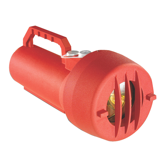
TL105 1.0 Introduction Figure 1: TL105 Test Lamp Notice All information contained in this instruction manual applies only to the setup and operation of the TL105 test lamp with flame detectors provided by General Monitors. The sale of the test lamp does not license the user to reproduce GM drawings or to utilize any information contained in this manual without prior written permission. -
Page 11: Description
TL105 Description The TL105 is a battery operated rechargeable test lamp specifically designed to test General Monitors’ UV, UV/IR, Digital Frequency IR, and Multi-Spectral IR flame detectors. The test lamp provides a high-energy, broadband radiation source that emits sufficient energy in both the ultraviolet and infrared spectra to activate UV and/or IR detectors. -
Page 12: Test Lamp Operating Principle
TL105 Figure 2: TL105 Battery Connection Test Lamp Operating Principle A variety of flashing test patterns, selectable through a rotary switch, allows the test lamp to check the operation of General Monitors flame detectors. When the specific flashing pattern for a given type of flame detector is appropriately selected, the test lamp triggers the alarm or test mode. -
Page 13: Quick Start Guide
TL105 2.0 Quick Start Guide 10-35 ft Figure 3: Approximate Distance between TL105 and a Flame Detector It is important to begin a series of flame detector checks with a fully charged TL105. Stand between 10 and 35 feet from a Flame Detector that is to be tested and aim the TL105 directly into the detector window. -
Page 14: Test Lamp Components
TL105 3.0 Test Lamp Components 3.1 Lamp Housing Assembly NOTE: Do not put fingerprints on the reflector or the light bulb, as this will reduce the available radiation required by the individual detector. The lamp housing assembly consists of a gold-plated parabolic reflector with the lamp affixed to its center. -
Page 15: Aluminum Case And Cap
TL105 lamp will turn itself off. This is to prevent the battery becoming completely discharged if the ON / OFF button is accidentally bumped on. 3.7 Aluminum Case and Cap The TL105 red aluminum housing is explosion proof for use in hazardous locations (8.2.2). It can also be used for general-purpose, non-hazardous applications. -
Page 16: Use And Operation
TL105 4.0 Use and Operation Figure 4: Reflector Mounting in Body Prior to opening of the test lamp make sure that the set screw located on the cap is loosened sufficiently to remove the cap. When closing, make sure that the captive screws (located on the reflector) are matched with the holes located on the body of the test lamp. -
Page 17: Figure 5: Location Of Functional Board Under Lamp Assembly
TL105 NOTE: Before testing any GM flame detector, see Table 2 and Figure 5 to ensure the rotary switch setting is correct for the particular detector. CAUTION: When operating in conditions involving fog, rain or frost, UV and IR radiation are (diminished) with increasing levels of moisture. -
Page 18: Table 2: Detector Test Mode Initiation Or/Detector Alarm Trigger With Tl105
TL105 Detector Test Mode Initiation or Detector Alarm Trigger with TL105 Flame Detector Rotary Switch Setting Maximum Distance to Results to Test Detector (ft) UV & UV/IR Type UV & UV/IR Type V & VI V & VI triggers into alarm mode FL3000 triggers into alarm FL3000 mode... -
Page 19: Test Lamp Maintenance And Warranty
TL105 5.0 Test Lamp Maintenance and Warranty 5.1 Maintenance Routine maintenance for the test lamp is minimal: When the test lamp is not being used, it is mandatory to ensure that the test lamp is docked on the charger and the charger is connected to a live 110 – 240VAC power supply adapter. -
Page 20: Recharging The Battery
TL105 5.3 Recharging the Battery Before the lamp is used for the first time, or after it has been used to the point where the red LED at the front has come on solidly, the battery must be recharged. To recharge the battery, take the test lamp to a non-hazardous area where there is no possibility of an explosive gas or dust atmosphere being present. - Page 21 TL105 of the equipment supplied by General Monitors. The customer will assume all liability for the misuse of this equipment by its employees or other personnel. All warranties are contingent upon proper use in the application for which the product was intended and do not cover products which have been modified or repaired without General Monitors’...
-
Page 22: Troubleshooting Guide
TL105 6.0 Troubleshooting Guide The following table lists potential problems that can affect the test lamp circuit. Follow the individual steps to pinpoint and define circuit ailments. This section is intended to be a guide in correcting problems, which may arise in the field. General Monitors should be contacted for assistance if the corrective action listed does not eliminate the problem. -
Page 23: Customer Support
TL105 7.0 Customer Support Area Phone/Email UNITED STATES 26776 Simpatica Circle Phone: +1-949-581-4464. 800-446-4872 Lake Forest, CA 92630 Email: info.gm@MSAsafety.com 9776 Whithorn Drive Houston, TX 77095 Phone: +1-281-855-6000 UNITED KINGDOM Heather Close Lyme Green Business Park Macclesfield, Cheshire, United Kingdom, SK11 0LR Phone: +44-1625-619-583 IRELAND Ballybrit Business Park... -
Page 24: Appendix
TL105 8.0 Appendix 8.1 Specifications Electrical specification 12 VDC 130 W Max Operating temperature: 5°F to +122°F (-15°C to +50°C) Storage temperature: 5°F to +122°F (-15°C to +50°C) Charging temperature 32°F to +104°F (0°C to +40°C) 10% to 90% 3% RH, non-condensing Humidity range: 7.9 lb (about 3.5 kg) Weight:... -
Page 25: Classification Area And Protection Methods
TL105 8.2.2 Classification Area and Protection Methods The TL105 is certified as follows: Protection Methods Ex db IIB+H T4 Gb Ex tb IIIC T110°C Db Area Classification Class I, Division 1 and 2, Groups C and D Conforms With EMC Directive (2014/30/EU) ATEX Directive (2014/34/EU) - Page 26 TL105 ADDENDUM This product may contain hazardous and/or toxic substances. EU Member states shall dispose according to WEEE regulations. For further WEEE disposal information please visit: www.MSAsafety.com All other countries or states: please dispose of in accordance with existing federal, state and local environmental control regulations.
Need help?
Do you have a question about the General Monitors TL105 and is the answer not in the manual?
Questions and answers