Table of Contents
Advertisement
Quick Links
M
TL105
ODEL
Test Lamp for Flame Detection
The inf ormation and technical data disclosed in
this document may be used and disseminated
only f or the purposes and to the extent
specifically authorized in writing by General
Monitors.
Instruction Manual
02-23
General Monitors reserves the right to change
published specifications and designs without
prior notice.
Part No.
MANTL105
Revision
M/02-23
CR
800000058477
Advertisement
Table of Contents

Related Manuals for MSA General Monitors TL105


Summary of Contents for MSA General Monitors TL105
- Page 1 TL105 ODEL Test Lamp for Flame Detection The inf ormation and technical data disclosed in this document may be used and disseminated only f or the purposes and to the extent specifically authorized in writing by General Monitors. Instruction Manual 02-23 General Monitors reserves the right to change published specifications and designs without...
- Page 2 TL105 This page is intentionally left blank.
- Page 3 TL105 NOTE THIS IS YELLOW PAPER WARNING: Do NOT leave battery uncharged. It will result in permanent battery damage.
- Page 4 TL105 Page intentionally left blank...
-
Page 5: Table Of Contents
TL105 Table of Contents MODEL TL105 ......................... I TEST LAMP FOR FLAME DETECTION ................... I ABOUT THIS MANUAL ......................VIII Format Conventions......................viii Notes, Cautions, and Warnings ................. viii Contacting Customer Support ................... viii 1.0 INTRODUCTION........................ 9 Notice ........................9 Special Warnings ...................... 9 Description ...................... - Page 6 TL105 Specif ications ......................23 Regulatory Agency Approvals ................... 23 8.2.1 Regulatory Agencies..................23 8.2.2 Classification Area and Protection Methods............24...
- Page 7 TL105 Table of Figures Figure 1: TL105 Test Lamp ........................9 Figure 2: TL105 Battery Connection .....................11 Figure 3: Approximate Distance between TL105 and a Flame Detector............12 Figure 4: Reflector Mounting in Body ....................15 Figure 5: Location of Functional Board under Lamp Assembly..............16 Table of Tables Table 1: Charge State Indicator ......................14 Table 2: Detector Test Mode Initiation or/Detector Alarm Trigger with TL105 ..........17...
-
Page 8: About This Manual
TL105 About This Manual This manual provides instructions for operating, and maintaining the General Monitors (GM) TL105 test lamp. The intended audience includes installation personnel, f ield service technicians, and other technical staff involved in using a TL105. Format Conventions Several f ormat conventions are used throughout this manual f or Notes, Cautions, and Warnings. -
Page 9: Introduction
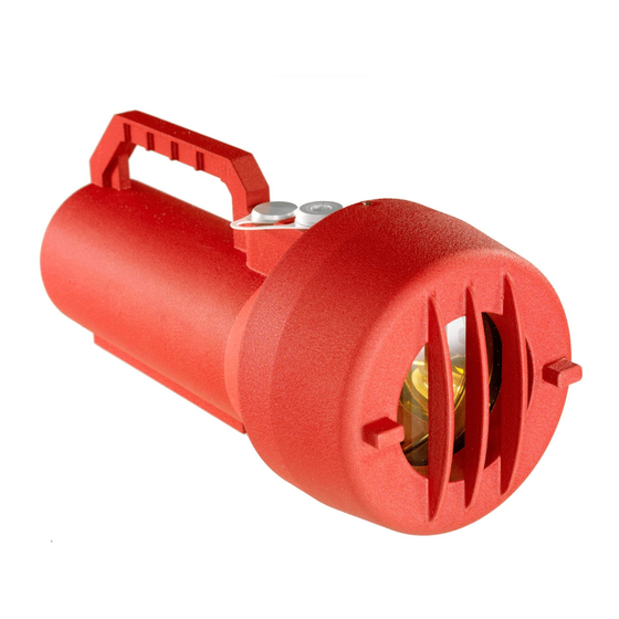
TL105 1.0 Introduction Figure 1: TL105 Test Lamp 1.1 Notice All inf ormation contained in this instruction manual applies only to the setup and operation of the TL105 test lamp with flame detectors provided by General Monitors. The s ale of t he t est lamp does not license the user to reproduce GM drawings or to utilize any inf ormation contained in this manual without prior written permission. -
Page 10: Description
TL105 Description The TL105 is a battery operated rechargeable test lamp specifically designed to tes t General Monitors’ UV, UV/IR, Digital Frequency IR, and Multi-Spectral IR f lame detectors. The test lamp provides a high-energy, broadband radiation source that emits suffic ient energy in b ot h t he ultraviolet and infrared spectra to activate UV and/or IR detectors. -
Page 11: Test Lamp Operating Principle
TL105 Figure 2: TL105 Battery Connection Test Lamp Operating Principle A variety of flashing test patterns, selectable through a rotary switch, allows t he t est lamp t o check the operation of General Monitors flame detectors. When the specific flashing pattern for a given type of flame detector is appropriately selected, the test lamp triggers the alarm or t est mode. -
Page 12: Quick Start Guide
TL105 2.0 Quick Start Guide 10-35 f t Figure 3: Approximate Distance between TL105 and a Flame Detector It is important to begin a series of flame detector checks with a fully charged TL105. Stand between 10 and 35 feet from a Flame Detector that is to be tested and aim t he •... -
Page 13: Test Lamp Components
TL105 3.0 Test Lamp Components 3.1 Lamp Housing Assembly NOTE: Do not put fingerprints on the reflector or the light bulb, as this will reduce the available radiation required by the individual detector. The lamp housing assembly consists of a gold-plated parabolic reflector with the lamp affixed to its center. -
Page 14: Aluminum Case And Cap
TL105 lamp will turn itself off. This is to prevent the battery becoming completely disc harged if t he ON / OFF button is accidentally bumped on. 3.7 Aluminum Case and Cap The TL105 red aluminum housing is explosion proof for use in hazardous locations (8.2.2). It can also be used for general-purpose, non-hazardous applications. -
Page 15: Use And Operation
TL105 4.0 Use and Operation Figure 4: Reflector Mounting in Body Prior to opening of the test lamp make sure that the set screw located on the cap is loosened suf ficiently to remove the cap. When closing, make sure that the captive screws (located on the reflector) are mat ched wit h the holes located on the body of the test lamp. -
Page 16: Figure 5: Location Of Functional Board Under Lamp Assembly
TL105 NOTE: Bef ore testing any GM flame detector, see Table 2 and Figure 5 to ensure t he ro tary switch setting is correct for the particular detector. CAUTION: When operating in conditions involving fog, rain or frost, UV and IR rad iation are (diminished) with increasing levels of moisture. -
Page 17: Table 2: Detector Test Mode Initiation Or/Detector Alarm Trigger With Tl105
TL105 Detector Test Mode Initiation or Detector Alarm Trigger with TL105 Flame Detector Rotary Switch Setting Maximum Distance to Results to Test Detector (ft) UV & UV/IR Type UV & UV/IR Type V & VI V & VI triggers into alarm mode FL3000 triggers into alarm FL3000 mode... -
Page 18: Test Lamp Maintenance And Warranty
TL105 5.0 Test Lamp Maintenance and Warranty 5.1 Maintenance Routine maintenance for the test lamp is minimal: When the test lamp is not being used, it is mandatory to ensure that the test lamp • is docked on the charger and the charger is connected to a liv e 110 – 240V A C power supply adapter. -
Page 19: Recharging The Battery
TL105 5.3 Recharging the Battery Bef ore the lamp is used for the first time, or after it has been used to the point where t he red LED at the f ront has come on solidly, the battery must be recharged. To recharge the bat tery, take the test lamp to a non-hazardous area where there is no possibility of an explosive gas or dust atmosphere being present. - Page 20 TL105 of the equipment supplied by General Monitors. The customer will assume all liability f or t he misuse of this equipment by its employees or other personnel. All warranties are contingent upon proper use in the applicat ion for whic h t he produc t was intended and do not cover products which have been modified or rep aired wit hout General Monitors’...
-
Page 21: Troubleshooting Guide
TL105 6.0 Troubleshooting Guide The f ollowing table lists potential problems that can affect t he t est lamp c irc uit. Fo llow t he individual steps to pinpoint and define circuit ailments. This section is intended to be a guide in correcting problems, whic h may arise in t he f ield. General Monitors should be contacted for assistance if the corrective ac tion list ed does not eliminate the problem. -
Page 22: Customer Support
Republic of Ireland, H91 H6P2 Email: inf o.gmil@MSAsafety.com SINGAPORE 35 Marsiling Ind. Estate, Road 3 #04-01 Phone: +65-6350 4500 Singapore 739257 Email: msa.singapore@MSAsafety.com MIDDLE EAST PO Box 54910 Dubai Airport Free Zone Phone: +971-299-6741 United Arab Emirates Email: gmdubai.main@MSAsafety.com Table 4: Locations Additional locations can be found on our web site, www.MSAsafety.com... -
Page 23: Appendix
TL105 8.0 Appendix 8.1 Specifications Electrical specification 12 VDC 130 W Max Operating temperature: 5°F to +122°F (-15°C to +50°C) Storage temperature: 5°F to +122°F (-15°C to +50°C) Charging temperature 32°F to +104°F (0°C to +40°C) Humidity range: 10% to 90% ± 3% RH, non-condensing Weight: 7.9 lb (about 3.5 kg) Dimensions:... - Page 24 TL105 8.2.2 Classification Area and Protection Methods The TL105 is certif ied as follows: Protection Methods Ex db IIB+H T4 Gb • Ex tb IIIC T110°C Db Area Classification Class I, Division 1 and 2, Groups C and D • Conf orms With EMC Directive (2014/30/EU) •...
- Page 25 TL105 ADDENDUM This product may contain hazardous and/or toxic substances. EU Member states shall dispose according to WEEE regulations. For further WEEE disposal information please visit: www.MSAsafety.com All other countries or states: please dispose of in accordance with existing federal, state and local environmental control regulations.
Need help?
Do you have a question about the General Monitors TL105 and is the answer not in the manual?
Questions and answers