Table of Contents
Advertisement
NATURAL GAS MODELS:
PROPANE GAS MODELS:
SAFETY INFORMATION
WARNING
!
FIRE OR EXPLOSION HAZARD
Failure to follow safety warnings exactly
could result in serious injury, death, or
property damage.
- Do not store or use gasoline or other
flammable vapors and liquids in the vicinity of
this or any other appliance.
- WHAT TO DO IF YOU SMELL GAS:
•
Do not try to light any appliance.
•
Do not touch any electrical switch; do not
use any phone in your building.
•
Immediately call your gas supplier from a
neighbour's phone. Follow the gas
supplier's instructions.
•
If you cannot reach your gas supplier, call
the fire department.
- Installation and service must be performed
by a qualified installer, service agency, or the
supplier.
This appliance may be installed in an aftermarket,
permanently located, manufactured home (USA
only) or mobile home, where not prohibited by
local codes.
This appliance is only for use with the type of gas
indicated on the rating plate. This appliance is
not convertible for use with other gases, unless
a certified kit is used.
INSTALLER:
Leave this manual with the appliance
CONSUMER:
Retain this manual for future reference
Wolf Steel Ltd., 24 Napoleon Rd., Barrie, ON, L4M 0G8 Canada / 103 Miller Drive, Crittenden, Kentucky, USA, 41030
$10.00
CBHD4PN / CBHD4STN / CBHD4PGN / CBHD4STGN
ADD PRODUCT CODE HERE (TRADE GOTHIC LT STD FONT)
CBHD4PP / CBHD4STP / CBHD4PGP / CBHD4STGP
Phone 1 (866) 820-8686 • www.continentalfireplaces.com • ask@continentalfire.com
INSTALLATION AND
ADD MANUAL TITLE
OPERATION MANUAL
CERTIFIED TO THE CANADIAN AND AMERICAN NATIONAL STANDARDS:
CSA 2.22 AND ANSI Z21.50 FOR VENTED DECORATIVE GAS APPLIANCES
IF INSTALLATION + OPERATION, ADD SERIAL
CSA /
INTERTEK
LOGO
BARCODE LABEL ON THE OWNER'S MANUAL"
Product Name / Code
Builder Series
ADD ____ ILLUSTRATED
ADD PRODUCT IMAGE
FOR INDOOR USE ONLY
NUMBER LABEL HERE
IF SEPARATE MANUALS, ADD "PLACE
ENGLISH
(see price book)
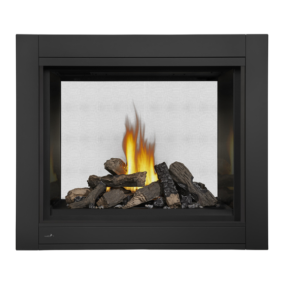
(CBHD4ST illustrated)
W415-1283 / F / 04.30.18
Advertisement
Table of Contents

Related Manuals for Continental Fireplaces CBHD4PN


Summary of Contents for Continental Fireplaces CBHD4PN
- Page 1 NATURAL GAS MODELS: CBHD4PN / CBHD4STN / CBHD4PGN / CBHD4STGN ADD PRODUCT CODE HERE (TRADE GOTHIC LT STD FONT) ENGLISH PROPANE GAS MODELS: CBHD4PP / CBHD4STP / CBHD4PGP / CBHD4STGP INSTALLATION AND ADD MANUAL TITLE OPERATION MANUAL Product Name / Code...
- Page 2 safety information WARNING • This appliance is hot when operated and DANGER • Any changes or alterations to this appliance or its controls can be dangerous and is prohibited. HOT GLASS WILL CAUSE • Do not operate appliance before reading and BURNS.
- Page 3 safety information WARNING • Do not allow wind or fans to blow directly into the appliance. Avoid any drafts that alter burner flame patterns. • Do not use a blower insert, heat exchanger insert or other accessory not approved for use with this appliance.
-
Page 4: Table Of Contents
table of contents general information finishing 35 rating plate / lighting instruction location 8 shipping bracket mobile home installation main safety barrier removal / installation dimensions end safety barrier removal / venting requirements installation (CBHD4P only) 36 typical vent installations main door removal / installation special vent installations end door removal / installation... - Page 5 Installer: please fill out the following information Customer: Address: Date of Installation: Location of appliance: Installer: Dealer/Distributor contact number: Serial #: Model: Natural Gas: CBHD4PN CBHD4STN Propane: CBHD4PP CBHD4STP CBHD4PGN CBHD4STGN CBHD4PGP CBHD4STGP Fuel Type Natural Gas Propane...
-
Page 6: General Information 6 Finishing
general information 1.0 general information When the appliance is installed at elevations above 4,500ft (1372m), and in the absence of specific recommendations from the local authority having jurisdiction, the certified high altitude input rating shall be reduced at the rate of 4% for each additional 1,000ft (305m). - Page 7 general information WARNING • Always light the pilot whether for the first time or if the gas supply has run out, with the glass door opened or removed. • Provide adequate clearance for servicing and operating the appliance. • Provide adequate ventilation. •...
-
Page 8: Rating Plate / Lighting Instruction Location
general information rating plate / lighting instruction location WARNING • Allow the appliance to cool before performing any maintenance or cleaning. note: Screen must be removed to access rating plate / lighting instructions. Both the rating plate and lighting instructions are attached to a cable and located behind the control panel of the appliance. -
Page 9: Dimensions
2.0 dimensions dimensions 25 1/8" 638mm 8" 203mm 5" 12 13/16" 127mm 325mm RIGHT LEFT 34 3/16" SIDE SIDE SAFETY BARRIER 868mm 38 1/4" 841mm 2 1/16" 53mm 7 9/16" 43 1/4" 1099mm 192mm 7 9/16" GAS INLET 192mm CBHD4P ELECTRICAL INLET BHD4P ILLUSTRATED ILLUSTRATED... -
Page 10: Venting Requirements
3.0 venting requirements venting requirements WARNING • Risk of fire. Maintain specified air space clearances to vent pipe and appliance. • The vent system must be supported every 3’(0.9m) for both vertical and horizontal runs. Use support ring assembly W010-0067 or equivalent non-combustible strapping to maintain the minimum clearance to combustibles for both vertical and horizontal runs. - Page 11 venting requirements For optimum flame appearance and appliance performance, keep the vent length and number of elbows to a minimum. The air terminal must remain unobstructed at all times. Examine the air terminal at least once a year to verify that it is unobstructed and undamaged. Rigid and flexible venting systems must not be combined.
-
Page 12: Typical Vent Installations
venting requirements typical vent installations 16" min (40.6cm) 40 FT (12m) 36" (91.4cm) 24" (61cm) 38 1/4" 43" (109.2c (97.2cm) MIN PLU RISE* When venting, the horizontal run must be kept to a When terminating vertically, the vertical rise is a maximum of 20 feet (6m). -
Page 13: Special Vent Installations
venting requirements special vent installations periscope termination Use the periscope kit to locate the air termination above grade. The periscope must be installed so that when final grading is completed, the bottom air slot is located a 12" minimum of 12” (305mm) above grade. The maximum allowable vent length is (30.5cm) 10’... -
Page 14: Converting From 5/8" To 4/7" Venting
venting requirements converting from 5/8" to 4/7" venting Use Mill Pac to seal adapter to the appliance collars. Ue Mill Pac to seal adapter to the appliance collars. Use Mill Pac to seal adapter to the appliance collars. W415-1283 / F / 04.30.18... -
Page 15: Vent Terminal Clearances
venting requirements vent terminal clearances Covered balcony applications ††* ≤ 15 feet = 3 feet = 2 x ACTUAL (4.6m) (0.9m) note: INSTALLATIONS Wall terminals are for illustration purposes only. Size and shapes may vary. CANADA U.S.A. 12” (30.5cm) 12” (30.5cm) Clearance above grade, veranda porch, deck or balcony. -
Page 16: Vent Application Flow Chart
venting requirements vent application flow chart Top Exit Horizontal Termination Vertical Termination Vertical rise is equal Vertical rise is equal Vertical rise is less Vertical rise is less to or greater than the to or greater than the than horizontal run than horizontal run horizontal run horizontal run... -
Page 17: Horizontal Termination
venting requirements horizontal termination ) < (V See graph to determine the required vertical rise V for the required Simple venting configuration (only one 45° and 90° elbow) horizontal run H 11.9) 39 ( 30 (9.1) REQUIRED VERTICAL RISE IN FEET 20 (6.1) (METERS) V 10 (3.1) - Page 18 venting requirements ) > (V Simple venting configuration (only one See graph to determine the required vertical rise V for the 45° and 90° elbow) required horizontal run H 12.3 (3.8) REQUIRED 8.3 (2.5) VERTICAL RISE IN FEET (METERS)V 4.8 (1.5) 4.2 (1.3) (1.5) (3.1) 12.5 (4.6)
-
Page 19: Vertical Termination
venting requirements vertical termination ) < (V Simple venting configurations. See graph to determine the required vertical rise V for the required horizontal run H 40 (12.2) 30 (9.1) REQUIRED VERTICAL RISE 20 (6.1) IN FEET (METERS) V 10 (3.1) 3 (0.9) 10 (3.1) (1.5) - Page 20 venting requirements ) > (V Simple venting configurations. See graph to determine the required vertical rise V for the required horizontal run H 20 (6.1) 19 (5.8) REQUIRED VERTICAL RISE IN FEET 10 (3.1) (METERS) V 3 (0.9) (1.5) (7.6) (9.1) (3.1) (4.6)
-
Page 21: Framing
framing 4.0 framing note: When using optional finishing accessories, the framing dimensions and finishing materials may differ from what is outlined in the section below; refer to the leaflet instructions supplied in the accessory kit for specific framing and finishing specifications. WARNING •... -
Page 22: Framing
framing framing see-thru framing (CBHD4ST) A: MIN 22 1/8" (56.2cm) 46 1/2" [118cm] MAX 24 1/8" (61.3cm) 45 1/2" [115.6cm] peninsula framing (CBHD4P) A: MIN 22 1/8" (56.2cm) MAX 24 1/8" (61.3cm) 46 1/2" [118cm] B: MIN 42 1/2" (108cm) MAX 43 1/2"... -
Page 23: Minimum Clearance To Combustible Enclosures
framing minimum clearance to combustible enclosures IMPORTANT: This appliance requires a minimum inside enclosure height of 50" (127cm), measured from the bot- tom of the appliance. For temperature requirements, this area must be left unobstructed. note: This appliance is not load bearing. IMPORTANT: The firestop assembly provided must be used when the vent pipes pass through any walls or are terminated horizontally. -
Page 24: Venting Installation
5.0 venting installation venting installation WARNING • Ensure to unpack all loose materials from inside the firebox prior to connecting the gas and electrical supply • If your appliance is supplied with a remote, ensure the remote receiver is in the “OFF” position prior to connecting the gas and electrical supply to the appliance. -
Page 25: Horizontal Installation
venting installation horizontal installation WARNING • The firestop assembly must be installed with the vent shield to the top. • Terminals must not be recessed into a wall or siding more than the depth of the return flange of the mounting plate. -
Page 26: Using Flexible Vent Components
venting installation using flexible vent components WARNING • Do not allow the inner flex pipe to bunch up on horizontal or vertical runs and elbows. Keep it pulled tight. • Spacers are attached to the inner flex pipe at predetermined intervals to maintain an even air gap to the outer flex pipe. -
Page 27: Horizontal Air Terminal Installation
venting installation horizontal air terminal installation Stretch the inner flex pipe to the required length taking Screws ADD FASTENER TYPE into account the additional length needed for the finished Red RTV Silicone Inner Coupler wall surface. Apply a heavy bead of the red RTV silicone Outer Coupler (W573-0002) (not supplied) to the inner sleeve of the air terminal. -
Page 28: Vertical Air Terminal Installation
venting installation vertical air terminal installation WARNING • Maintain a minimum 2” (51mm) space between the air inlet base and the storm collar. note: Fastening hardware provided with appropriate roof terminal and liner kits. Fasten the roof support to the roof using 6 screws. The roof support is optional. -
Page 29: Electrical Information
6.0 electrical information electrical information hard wiring connection It is necessary to hard wire this appliance. Permanently framing the appliance with an enclosure, requires the appliance junction box to be hard wired. This appliance must be electrically connected and grounded in accordance with local codes. In the absence of local codes, use the current CSA C22.1 Canadian electrical code in Canada or the ANSI/NFPA national electrical code in the United States. -
Page 30: Battery Back-Up Installation
electrical information battery back-up installation note: In the event of a power failure, your appliance can be operated using the supplied battery back-up. A. Remove the safety barrier and door, refer to the "main safety barrier removal / installation" and "main door removal / installation"... -
Page 31: Wiring Diagram
electrical information wiring diagram WARNING • Do not wire 110 volts to the valve or wall switch. ACS/IPI SWITCH (OPTIONAL) GREEN ON / OFF ORANGE SWITCH TRANSFORMER IPI / CPI ON / OFF BATTERY HOUSING ELECTRONIC DISCONNECT THESE VALVE CONNECTIONS TO THE ON/OFF SWITCH. -
Page 32: Gas Installation
7.0 gas installation electrical information WARNING • Risk of fire, explosion, or asphyxiation. Ensure there are no ignition sources such as sparks or open flames. • Support gas control when attaching gas supply pipe to prevent damaging gas line. • Always light the pilot whether for the first time or if the gas supply has run out with the glass door opened or removed. -
Page 33: Nailing Tab Installation
8.0 nailing tab installation nailing tab installation Nailing tabs are provided as part of the frames, as shown. To determine the final location and where to bend the nailing tabs you must first determine the thickness of your finishing material (i.e. NAILING IMAGE drywall). -
Page 34: Operating Instructions
operating instructions 9.0 operating instructions When lit for the first time, the appliance will emit a slight odour for a few hours. This is a normal temporary condition caused by the “burn-in” of internal paints and lubricants used in the manufacturing process and will not occur again. -
Page 35: Shipping Bracket
finishing 10.0 finishing WARNING • Risk of fire! • Never obstruct the front opening of the appliance. • The front of the appliance must be finished with any non-combustible materials such as brick, marble, granite, etc., provided that these materials do not go below the specified dimension, as illustrated. •... -
Page 36: End Safety Barrier Removal / Installation (Cbhd4P Only)
finishing end safety barrier removal / installation (CBHD4P only) note: One of the main safety barriers must be removed prior to end barrier removal, see "main safety barrier removal / installation" section. Remove the 4 securing screws from the top and bottom of the end screen retainer, refer to Figure 1. Pull the safety barrier forward and out from the appliance, refer to Figure 2. -
Page 37: Main Door Removal / Installation
finishing main door removal / installation WARNING • Glass may be hot. Do not touch glass until cooled. • If equipped with door latches that are part of a safety system, they must be properly engaged. Do not operate the appliance with latches disengaged. •... -
Page 38: End Door Removal / Installation
finishing end door removal / installation (CBHD4P only) note: One of the main safety barriers and doors must be removed prior to end barrier removal, see "main safety barrier removal / installation" section and "main door removal / installation" sections for detailed instructions. Remove the 6 screws securing the end door in place, as shown below. -
Page 39: Installing Combustible Board
finishing installing combustible board WARNING • The surface above the appliance gets very hot. If proper finishing materials are not used, cracking can occur. • Ensure clearances are maintained for surround removal, as it must lift off the appliance for maintenance. BHD4ST BHD4P SIDE... -
Page 40: 10.7.1 Finishing Support Adjustment
finishing 10.7.1 finishing support adjustment Depending on the finishing material we have allowed from 0" (0mm) to 1" (25mm) of adjustment after the 1/2" (13mm) combustible board has been installed. Loosen the 8 screws on each finishing support. Adjust the finishing support to the desired position. -
Page 41: Minimum Mantel Clearances
finishing minimum mantel clearances WARNING • Risk of fire. Maintain all specified air space clearances to combustibles. Failure to comply with these instructions may cause a fire or cause the appliance to overheat. Ensure all clearances (i.e. back, side, top, vent, mantel, front, etc.) are clearly maintained. -
Page 42: Non-Combustible Facing Material
finishing non-combustible facing material WARNING Non-combustible facing material must not project more than 4” (101.6mm) from the face of the door (all four sides). If greater projections are desired, increase the clearance to the sides, bottom and top by 2” (50.8mm) for every additional 1”... -
Page 43: Log Placement
finishing log placement WARNING • Failure to position the logs in accordance with these diagrams or failure to use only logs specifically approved with this appliance may result in property damage or personal injury. • Logs must be placed in their exact location in the appliance. Do not modify the proper log positions, since appliance may not function properly and delayed ignition may occur. - Page 44 finishing 7. Place log #6 onto the pin located on the right side corner of the burner, then place one pin into middle of the log #6 and log #5 (Fig. 6). Fig. 6 note: Ensure log #6 does not cover any burner ports. 8.
-
Page 45: Glowing Embers Charcoal Embers
finishing glowing embers WARNING • Do not block or close off the burner ports. Blocked ports can cause an incorrect flame pattern, carbon deposits and delayed ignition. Tear the embers into pieces and loosely layer above the burner ports covering the burner area. Care should be taken to shred the embers into thin, small irregular pieces as only the exposed edges of the fibre hairs will glow. -
Page 46: Glass Media Installation
finishing glass media installation WARNING • Clean the glass media prior to installation. Before applying the cleaned glass, ensure that it is dry. • Do not change or substitute the glass media material provided with this appliance. If replacing, use only the replacement glass media available from your local authorized dealer / distributor. -
Page 47: Anti-Condensation Switch
finishing anti-condensation switch note: End safety barrier must be removed before accessing the anti-condensation switch, see "end safety barrier removal / installation (CBHD4P only)" section for detailed instructions. This appliance has the ability to switch from an electronic intermittent pilot ignition (IPI) to a standing pilot (ACS) for cold climates. -
Page 48: Adjustments
11.0 adjustments adjustments pilot burner adjustment Adjust the pilot screw to provide properly sized flame. Turn in a clockwise direction to reduce the gas flow. Check Pressure Readings: Inlet pressure can be checked by turning screw (A) counter- clockwise 2 or 3 turns and then placing pressure gauge tubing over the test point. -
Page 49: Flame Characteristics
adjustments flame characteristics FLAME SENSOR 3/8” - 1/2” PILOT (9.5mm - 12.7mm) It’s important to periodically perform a visual check of BURNER ELECTRODE the pilot and burner flames. Compare them to the ADD IMAGE illustration provided. If any flames appear abnormal, call a service person. -
Page 50: Maintenance
12.0 maintenance maintenance WARNING • Turn off the gas and electrical power before servicing the appliance. • Appliance may be hot. Do not service until appliance has cooled. • Do not use abrasive cleaners on glass. • Do not paint the pilot assembly. This appliance and its venting system should be inspected before use and at least annually by a qualified service person. -
Page 51: Care Of Glass
maintenance care of glass WARNING • Do not clean glass when hot! Do not use abrasive cleaners to clean glass. Buff lightly with a clean dry soft cloth to remove accumulated dust or fingerprints. Clean both sides of the glass after the first 10 hours of operation with an ammonia-free glass cleaner. -
Page 52: Glass / Door Replacement
maintenance glass / door replacement WARNING • Do not use substitute materials. • Glass may be hot. Do not touch glass until cooled. • Care must be taken when removing and disposing of any broken door glass or damaged components. Be sure to vacuum up any broken glass from inside appliance before operation. -
Page 53: Glass Burner Removal
maintenance glass burner removal Remove the main door(s) from the appliance, see "main door removal / installation" section for detailed removal instructions. Vacuum the glass media out of the appliance. Ensure you insert a clean bag into your vacuum cleaner. Remove the 12 screws securing the media tray, then remove the media tray from the appliance, as shown below. -
Page 54: Replacements
replacements 13.0 replacements WARNING • Failure to position the parts in accordance with this manual or failure to use only parts specifically approved with this appliance may result in property damage or personal injury. • **This is a fast acting thermocouple. It is an integral safety component. Replace only with a fast acting supplied by Wolf Steel Ltd. -
Page 55: Cbhd4P Overview
CBHD4P overview Safety screen Safety screen For replacement parts, refer to: For replacement parts, refer to: Safety screen “glass burner assembly” “log burner assembly” For replacement parts, refer to: For replacement parts, refer to: “log burner valve train assembly” “glass burner valve train assembly” Items may not appear exactly as illustrated Ref. -
Page 56: Cbhd4St Overview
CBHD4ST overview Safety screen Safety screen For replacement parts, refer to: For replacement parts, refer to: “glass burner assembly” section. “log burner assembly” section. For replacement parts, refer to: For replacement parts, refer to: “log burner valve train assembly” section. “glass burner valve train assembly”... -
Page 57: Glass Burner Assembly
glass burner assembly Items may not appear exactly as illustrated. Ref. No. Part number Description Stocked W010-2954-SER Burner assembly W080-1400-SER Burner bracket W290-0018 Venturi gasket W720-0005 Venturi... -
Page 58: Glass Burner Valve Train Assembly
glass burner valve train assembly 1 1 1 0 1 1 2 1 1 1 3 2 1 1 3 4 1 1 3 5 1 1 3 6 Items may not appear exactly as illustrated Ref. No. Part number Description Stocked Ref. -
Page 59: Log Burner Assembly
log burner assembly Items may not appear exactly as illustrated Ref. No. Part number Description Stocked Ref. No. Part number Description Stocked W010-2955 Burner assembly W720-0005 Venturi W080-1463 Burner bracket W080-1399 Burner bracket W290-0018 Venturi gasket... -
Page 60: Log Burner Valve Train Assembly
log burner valve train assembly 1 1 0 1 1 1 1 2 1 1 2 3 1 1 3 4 1 1 2 5 1 1 3 6 Items may not appear exactly as illustrated Ref. No. Part number Description Stocked Ref. -
Page 61: Accessories Troubleshooting
Front side view GL-688 Rear side view PRPHD4 GD851KT Items may not appear exactly as illustrated Ref. No. Part number Description Stocked Ref. No. Part number Description Stocked LDAC Designer fire art coil design W135-0530 Log #4 LDNS Designer fire art nickel stix W135-0531 Log #5 MEGK... - Page 62 troubleshooting 15.0 troubleshooting WARNING • Always light the pilot whether for the first time or if the gas supply has run out, with the glass door open or removed. • Turn off gas and electrical power before servicing the appliance. •...
- Page 63 troubleshooting symptom problem test solution Verify the thermocouple/sensor is clean and the wiring is undamaged. Pilot will not light. Makes Wiring: short, loose, or damaged Verify the interrupter block is not damaged or too tight. Verify noise with no spark at connections connections from pilot assembly are tight;...
- Page 64 troubleshooting symptom problem test solution Motor is turning, Receiver batteries low. Replace batteries. frequent beeping occurs. Verify ON/OFF switch is in the “I” position which denotes on. Lights or blower Control module switch in won’t function (if wrong position. equipped). Verify “COM”...
- Page 65 16.0 warranty warranty Continental® products are manufactured under the strict standard of the world recognized ISO 9001 : 2015 Quality Management System. Continental® products are designed with superior components and materials assembled by trained craftsmen who take great pride in their work. The burner and valve assembly are leak and test-fired at a quality test station. The complete appliance is again thoroughly inspected by a qualified technician before packaging to ensure that you, the customer, receives the quality product that you expect from Continental®.
- Page 66 7200, Route Transcanadienne, Montréal, Québec H4T 1A3 24 Napoleon Road, Barrie, Ontario, Canada L4M 0G8 214 Bayview Drive, Barrie, Ontario, Canada L4N 4Y8 103 Miller Drive, Crittenden, Kentucky, USA 41030 Phone: 1-866-820-8686 continentalfireplaces.com...
Need help?
Do you have a question about the CBHD4PN and is the answer not in the manual?
Questions and answers