BEKA BA327E-SS Manual

BEKA BA327E-SS Manual

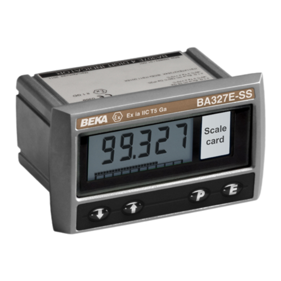
Intrinsically safe loop-powered rugged panel mounting indicators

Advertisement

BA307E-SS & BA327E-SS
intrinsically safe
loop-powered
rugged
panel mounting indicators
Issue 3
Issue: 3
4
th
May 2017

Advertisement

Table of Contents
loading
Need help?

Need help?

Do you have a question about the BA327E-SS and is the answer not in the manual?

Questions and answers

Summary of Contents for BEKA BA327E-SS

  • Page 1 BA307E-SS & BA327E-SS intrinsically safe loop-powered rugged panel mounting indicators Issue 3 Issue: 3 May 2017...
  • Page 2: Table Of Contents

    Appendix 1 ATEX dust certification Appendix 2 IECEx gas and dust certification Appendix 3 FM and cFM certification The BA307E-SS & BA327E-SS are CE marked to show compliance with the European Explosive Atmospheres Directive 94/9/EC and the European EMC Directive 2004/108/EC...
  • Page 3: Description

    BA307E-SS 4 digits 15mm high all segments of the display are activated, after five seconds the instrument displays the input current BA327E-SS 5 digits 11mm high using the calibration information stored in the and 31 segment bargraph. instrument memory.
  • Page 4: Controls

    P + E Access to configuration menu via optional security code. In gases that may be used with equipment having Note: * BA327E-SS only a temperature classification of: Φ If the indicator has been calibrated using the CAL function, calibration points may not be 4 and 20mA.
  • Page 5: Special Conditions For Safe Use

    It shows the ATEX certification information, instrument serial number, year of a. When installed in an Ex px, Ex py or Ex pz panel manufacture plus BEKA associates' name and enclosure the indicator must be powered by an location. IECEx certification information is also appropriately rated Zener barrier or galvanic included, a typical label is shown below.
  • Page 6: System Design For Gas Hazardous Areas

    4. SYSTEM DESIGN FOR GAS HAZARDOUS AREAS 4.1 Transmitter loops Both indicator may be connected in series with almost any intrinsically safe 4/20mA current loop and calibrated to display the measured variable or control signal in engineering units. There are three basic design requirements: 1.
  • Page 7: Use In Ex E Panel Enclosure In Zone

    4.3.1 Installation in an Ex e panel enclosure within Zone 1 or Zone 2. Installation of a BA307E-SS or BA327E-SS indicator in an Ex e IIC Gb increased safety panel enclosure does not invalidate the Ex e panel's ingress and impact protection as the front of both indicators comply with Ex e impact and ingress requirements.
  • Page 8 4.3.2 Installation in Ex p panel enclosure within Zone 1 or Zone 2. Installation of a BA307E-SS or BA327E-SS indicator in an Ex p IIC Gb or Ex p IIC Gc pressurised panel enclosure does not invalidate the Ex p panel's impact and ingress protection as the front of both indicators comply with Ex p impact and ingress requirements.
  • Page 9: Installation

    The BA307E-SS and BA327E-SS may be located in d. Slide a panel clamp into the two grooves at Zone 0, 1 or 2 providing that the operating each corner of the indicator housing with the temperature is between –40°C and +70°C and the...
  • Page 10: Indicator Earthing

    A pack of self-adhesive scale cards printed with common units of measurement is available as an accessory from BEKA associates. Custom printed scale cards can also be supplied. To change a scale card, unclip the protruding end of the flexible strip by gently pushing it upwards and pulling it out of the enclosure.
  • Page 11: Configuration And Calibration

    If calibration is not requested, indicators will be configured as follows: 'SEt' Calibration of display using internal references. BA307E-SS BA327E-SS Enables the zero and span of the Access code ‘CodE’ 0000 0000 indicator to be adjusted without the Function ‘FunC’...
  • Page 13 Display Summary of function 6.2 Indicator function: ‘FunC’ This configuration function defines the relationship 'C - - P' Function of P push-button between the indicator’s 4/20mA input current and The indicator may be configured to display the indicator’s display. Three alternatives are the input current in milliamps, or the input available: current as a percentage of the 4/20mA...
  • Page 14: Calibration Using An External

    In addition to a five digit numerical display the ▼ buttons, when set s required pressing P will BA327E-SS has a 31 segment analogue bargraph transfer control to the next digit. When all the digits which may be configured to start and finish...
  • Page 15: Function Of The P Push-Button

    E to return to the ‘tARE’ prompt in instrument will display ‘LPLo’ before it stops the configuration menu. functioning. Under or overrange of the BA327E-SS bargraph is 6.10 Security code: ‘CodE’ indicated by an activated arrow at the appropriate Access to the instrument configuration menu may be end of the bargraph and a flashing bargraph scale.
  • Page 16: Lineariser Calibration Using An External Current Source

    7. LINEARISER 7.1 Lineariser calibration using an external A sixteen segment, seventeen break-point (0 to 16) current source. lineariser may be selected in the ‘FunC’ section of the This method allows direct calibration of the configuration menu. The position of each break-point lineariser with an external current source and is the is fully adjustable so that the slope of the straight line preferred method when traceability is required.
  • Page 18: Lineariser Calibration Using Internal Reference

    The delete break-point sub-function 'dEL' operates in add the second additional break-point by operating exactly the same way as the 'Add' sub-function the P push button which will result in a display of described above. Once within the ‘dEL’ sub-function '2:3'.
  • Page 19: Example, Adding Break-Points To A New Indicator

    ‘LtAb’ function described in section 6.11, button. the defaults conditions are: Indicator display The corresponding indicator display at each of the BA307E-SS BA327E-SS break-points can now be defined using the ‘diSP’ sub- First break-point '0:1' 0.00 Second break-point '1:1' 20mA 100.0 100.00...
  • Page 20: Maintenance

    Indicators which fail within the guarantee period displayed or overrange. should be returned to BEKA associates or our local Unstable display 4/20mA input is Reduce ripple on agent. It is helpful if a brief description of the fault noisy.
  • Page 21: Accessories

    9. ACCESSORIES 9.1 Scale card Both models have a window on the right hand side of the display through which to view a scale card showing the units of measurement such as C, mBar, RPM. New indicators are fitted with a scale card showing the units of measurement specified when the indicator was ordered, if the units are not specified a blank scale card will be fitted.
  • Page 23: Alarm Enable

    ‘SEt’ and the ‘C- - P’ functions for the activated. BA307E-SS and and between ‘bAr’ and ‘C- -P’ for the See section 9.3.11 BA327E-SS indicators. For simplicity, Fig 15 only shows the additional functions for alarm 1, but alarm 2 'ACSP' Access setpoint has identical functions.
  • Page 24 9.3.4 Alarm enable: ‘EnbL’ To check or change the alarm output status, select This function allows each alarm to be enabled or 'no.nC' from the alarm configuration menu and disabled without altering any of the alarm parameters. press P to reveal the setting. The function may be To enable or disable the alarm select 'EnbL' from the changed by pressing the ▲...
  • Page 25: Access Setpoint In Display

    9.3.10 Alarm silence time: SiL function in the alarm configuration menu as shown This function is primarily intended for use in small in Fig 15. To change the menu parameters select installations where the alarm output directly operates 'ACSP' from the configuration menu and press P an alarm annunciator such as a sounder or beacon.
  • Page 26: Displaying Setpoints On Bargraph

    9.3.14 Displaying setpoints on bargraph One of the selectable bargraph formats ‘AlrSP’ allows a low or a high setpoint plus the displayed value to be represented, or a low and a high setpoint plus the displayed value to be represented by the bargraph as shown in Fig 18.
  • Page 27: Display Backlight

    9.4 Display backlight 9.4.2 Separately powering the backlight The BA307E-SS and BA327E-SS loop powered The optional backlight may also be powered from a indicators can be supplied with a factory fitted separate safe area power supply via an intrinsically backlight that may be loop or separately powered.
  • Page 28 Zones, and Maximum Surface Temperature Both models have IP66 front of panel protection The BA307E-SS and the BA327E-SS have been and a gasket is provided to seal the joint between ATEX certified as Group II, Category 1D Ex ia IIIC the instrument and the mounting panel thus T80ºC Da IP20 apparatus, Ta -40 to 70°C.
  • Page 29 Zone 21 or Zone 22. apparatus is usually installed in the safe area, but Installation of a BA307E-SS or BA327E-SS indicator the inside of an Ex t enclosure is effectively a safe in an Ex t IIIC panel enclosure does not invalidate the...
  • Page 30 When installed in an Ex px, Ex py or Ex pz information about the IECEx certification scheme and panel enclosure the indicator must be powered to view the BEKA associate certificates, please visit by an appropriately rated Zener barrier or www.iecex.com galvanic isolator located in a safe area.
  • Page 31 BA307E-SS or a BA327E-SS will not invalidate the certification of an AEx e, AEx p or AEx n panel enclosure. Providing that the local code of practice is followed, this allows the indicators to be installed as shown in sections 4.3.1 and 4.3.2 of this manual.

This manual is also suitable for:

Ba307e-ss

Table of Contents