
Related Manuals for BEKA BA307SE


Summary of Contents for BEKA BA307SE
- Page 1 BA307SE & BA327SE Ex ec & Ex tc loop-powered panel mounting indicators Issue 4 Issue: 4 26th September 2023...
-
Page 2: Table Of Contents
7.4 Under and over-range 7.5 Lineariser default configuration The BA307SE & BA327SE panel mounting indicators are CE marked to show compliance with the European Explosive Atmospheres Directive 2014/34/EU and the European EMC Directive 2014/30/EU. The indicators are also UKCA marked to show compliance with UK statutory requirements Equipment and Protective Systems Intended for Use in Potentially Explosive Atmospheres Regulations UKSI 2016:1107 (as amended) and with the Electromagnetic Compatibility Regulations UKSI 2016:1091 (as amended). -
Page 3: Description
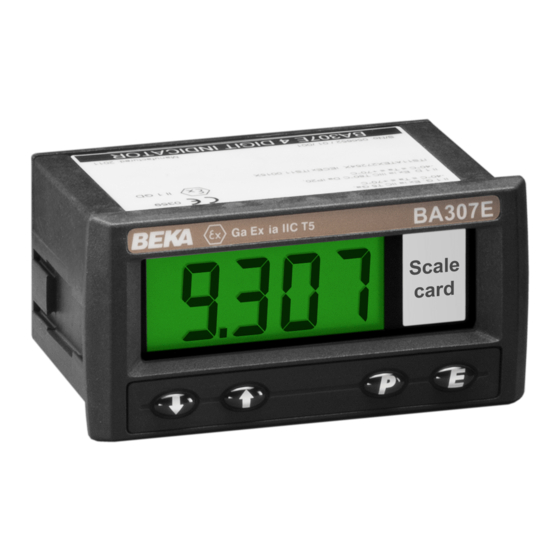
Each time a 4/20mA current is applied to the Model Display instrument initialisation is performed during which BA307SE 4 digits 15mm high all segments of the display are activated, after five seconds the instrument displays the input current BA327SE 5 digits 12.7mm high... -
Page 4: Controls
Code of Practice should always be consulted. Fig 2 shows the certification No function in the display mode unless information label that is on the top of a BA307SE the tare function is being used. indicator. &... -
Page 5: Zones, Gas Groups & T Rating
EN/IEC 60079-0 Clause 1 and provide at least IP54 ingress protection as required by IEC 60079-7. Mounting the BA307SE or BA327SE in an Ex e component certified enclosure satisfies these At ambient temperatures between -40 and requirements, but component certificates are only intended to be used as part of a certified assembly. -
Page 6: System Design For Zone 2 Gas
Figs 2 illustrate a typical application in which a BA307SE or BA327SE located in Zone 2 is connected in series with a 2-wire Ex d transmitter located in Zone 1. -
Page 7: Remote Indication
4.2 Remote indication containing a fuse holder with an easily removable The BA307SE and the BA327SE may also be fuse which can be extracted to achieve isolation. driven directly from a safe area instrument with a... -
Page 8: Installation
4J impact. This component Ex e certification M3 stud protruding through the hole at the confirms that when a BA307SE or BA327SE rear of the clamp. Fit the stainless steel indicator is installed in an Ex e enclosure the... -
Page 9: Indicator Earthing
A pack of self-adhesive scale cards printed with common units of measurement is available as an accessory from BEKA associates. Custom printed scale cards can also be supplied. To change a scale card, unclip the protruding end of the flexible strip by gently pushing it upwards and pulling it out of the enclosure. -
Page 11: Configuration And Calibration
Enables the zero and span of the indicator to be adjusted without the Default Configuration need for an accurate input current or BA307SE BA327SE Access code code 0000 0000 disconnection from the 4/20mA loop. Function func... - Page 12 Display Summary of function 6.2 Indicator function: func This configuration function defines the relationship Function of ( push button between the indicator’s 4/20mA input current and c - - p The indicator may be configured to the indicator’s display. Three alternatives are display the input current in milliamps, or available: the input current as a percentage of the...
-
Page 13: Calibration Using An External
6.4 Position of the decimal point: dp 6.6 Calibration using internal reference: 5et A dummy decimal point can be positioned between Using the 5et function the indicator can be any of the digits or it may be absent. To position calibrated without the need to know the value of the decimal point select dP from the menu and the 4/20mA input current, or to disconnect the... -
Page 14: Reset To Factory Defaults
Please contact BEKA associates sales department if the security code is lost. Note: barlo must be set lower than barhi, incorrect setting is indicated by the bargraph scale flashing with a single bargraph segment activated. -
Page 15: Lineariser Calibration Using An External Current Source
7. LINEARISER 7.1 Lineariser calibration using an external A sixteen segment, seventeen breakpoint (0 to 16) current source. lineariser may be selected in the func section of This method allows direct calibration of the the configuration menu. The starting point and lineariser with an external current source and is the slope of each straight line segment are fully preferred method when traceability is required. -
Page 17: Lineariser Calibration Using Internal Reference
CAUTION Note: The indicator input current must be When adding break-points to a new indicator, adjusted to the required value before the ( or following resetting of the lineariser to the button is operated to enter the required indicator factory defaults using the ltab function display. -
Page 18: Lineariser Error Message
The number of break-point required should first be Using the * or & button select in from the sub- entered using the add and del sub-functions. In menu and press ( which will reveal the starting both these sub-functions the indicator initially point for the first segment 0: n , where n is the total displays the current break-point and the total number of break-point entered. -
Page 19: Under And Over-Range
7.5 Lineariser default configuration When the lineariser is reset to the factory defaults using the ltab function described in section 6.11, the defaults conditions are: Indicator display BA307SE BA327SE First break-point 0.00 0: 1 Second break-point 1: 1 20mA 100.0... -
Page 20: Maintenance
We recommend that faulty instruments are Unable to enter Incorrect Enter correct returned to BEKA associates or to your local configuration security code security code, or BEKA agent for repair. menu. entered. contact BEKA if... -
Page 21: Routine Maintenance
8.5 Guarantee Indicators which fail within the guarantee period should be returned to BEKA associates or your local BEKA agent. It is helpful if a brief description of the fault symptoms is provided. 8.6 Customer comments BEKA associates is always pleased to receive comments from customers about our products and services. -
Page 22: Accessories
Custom printed cards showing less common units of configuration. The open circuit condition should of measurement are available from BEKA or can therefore be chosen as the alarm condition when be hand printed onto the scale card using a variety designing an alarm system. -
Page 23: Solid State Output
Clear identification of, and easy access to the means of isolation is essential for their effective Providing that the BA307SE or BA327SE indicator use. It is also necessary to ensure that the is correctly installed in a panel enclosure located in... -
Page 24: Configuration And Adjustment
Fig 16. The additional functions appear between the 5et and the c- - p functions for the BA307SE and between bar and c- -p for the BA327SE indicator. For simplicity, Fig 16 only shows the additional functions for alarm 1, but alarm 2 has identical functions. - Page 25 Display Summary of function 9.4.4 Alarm enable: enbl This function allows each alarm to be enabled or Alarm enable disabled without altering any of the alarm enbl Enables or disables the alarm without parameters. To enable or disable the alarm select changing the alarm parameters.
-
Page 26: Alarm Delay
CAUTION e.g. An indicator with a high alarm set at 9000 and When the 4/20mA supply is removed from the an alarm delay of 30 seconds will perform as loop powered indicator, both alarm outputs follows: will open irrespective conditioning. Therefore for fail safe operation both alarm The alarm annunciator will start to flash when an outputs should be conditioned to be open in... -
Page 27: Access Setpoint In Display Mode
reference, alr1 or alr2, when the alarm output is 9.4.13 Adjusting alarm setpoints from the activated. If both alarm outputs are activated, the display mode alarm references are displayed in sequence. Access to the alarm setpoints from the indicator display mode is obtained by operating the ( and To enable or disable the function select fl5h from * push buttons simultaneously as shown in the alarm menu and press ( which will reveal the... -
Page 28: Displaying Setpoints On Ba327Se Bargraph
To adjust an alarm setpoint select 5p1 or 5p2 and 9.4.14 Displaying setpoints on BA327SE press ( which will reveal the current setting. bargraph One of the selectable bargraph formats alr5p Each digit of the setpoint may be adjusted using the * and &... -
Page 29: Display Backlight
9.5 Display backlight 9.5.2 Separately powering the backlight The BA307SE and BA327SE loop powered The optional backlight may also be powered from a indicators can be supplied with a factory fitted separate power supply as shown in Fig 21. backlight that may be loop or separately powered. - Page 30 Ex p pressurised panel enclosure located in a Zone 2 hazardous area. A1.2 Installation in a Zone 2 Ex p enclosure Installation of a BA307SE or BA327SE indicator in an Ex p pressurised panel enclosure does not invalidate the pressurised panel's ingress and...
-
Page 31: Appendix 2 Iecex, Atex And Ukex Dust Certification
Category 3D Ex tc ic IIIC T80°C Dc apparatus with described in the main section of this instruction a Ta of –40°C to +70C. Ex tc is dust ignition manual, the BA307SE and the BA327SE also have protection enclosure complying with Ex tc certification. - Page 32 A2.3 Maintenance The BA307SE and BA327SE front panel keypads are intrinsic safe Ex ic which allows them to be operated in Zone 22 The IEC guidance on maintenance procedures...
-
Page 33: Appendix 3 Etl & Cetl Certification
ETL & cETL certification for installations in USA and Canada. A3.0 cETL Mark For installations in the USA and Canada, the BA307SE and BA327SE indicators have ETL and cETL Ex ec and Ex tc approval. Copies of the Authorisation to Mark may be downloaded from the BEKA associates website www.beka.co.uk...
Need help?
Do you have a question about the BA307SE and is the answer not in the manual?
Questions and answers