
Related Manuals for BEKA BA327NE


Summary of Contents for BEKA BA327NE
- Page 1 BA307NE & BA327NE Ex nA & Ex tc loop-powered panel mounting indicators Issue 3 Issue: 3 Novemeber 2017...
-
Page 2: Table Of Contents
Appendix 4 ETL and cETL certification 7.3 Lineariser error message 7.4 Under and over-range 7.5 Lineariser default configuration The BA307NE & BA327NE are CE marked to show compliance with the European Explosive Atmospheres Directive 2014/34/EU and the European EMC Directive 2014/30/EU... -
Page 3: Description
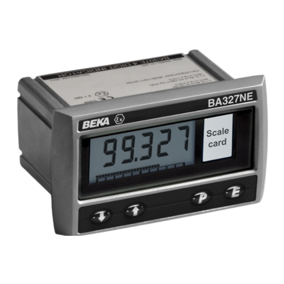
BA307NE 4 digits 15mm high all segments of the display are activated, after five seconds the instrument displays the input current BA327NE 5 digits 11mm high using the calibration information stored in the and 31 segment bargraph. instrument memory. -
Page 4: Controls
'X' suffix. These state that the indicators should be correctly mounted in a panel enclosure Notes: * BA327NE only complying with the requirements specified in Φ BS EN 60079-15:2010 for Equipment protection by If the indicator has been calibrated using the CAL function, calibration type of Protection 'n'. -
Page 5: 4/20Ma Input
Type of protection 'n', the panel enclosure containing the BA307NE or BA327NE may be installed in: Zone 2 explosive gas air mixture not likely to occur, and if it does will only exist for a short time. -
Page 6: System Design For Zone 2 Gas
24V, that is safe in normal operation 4.2 Remote indication and suitable for live connection i.e. CE The BA307NE and the BA327NE may also be marked, is usually considered acceptable. driven directly from a safe area instrument with a 3. - Page 7 Fig 3 Remote indication in Zone 2 hazardous area comply with requirements BS EN 60079:14 Electrical installations design, selection and erection, each of the wires entering the hazardous area should be individually fused and contain a means of isolation. These two requirements are frequently satisfied by using switch fuse holders with easily removable fuses which can be extracted to achieve isolation as...
-
Page 8: Installation
Ex e panel enclosures are frequently used as Ex n c. If the enclosure panel is less than 1.0mm panel enclosures. thick, or is non-metallic, an optional BEKA stainless steel support plate should be slid The indicators may also be installed in an Ex e or... -
Page 9: Indicator Earthing
A pack of self-adhesive scale cards printed with common units of measurement is available as an accessory from BEKA associates. Custom printed scale cards can also be supplied. To change a scale card, unclip the protruding end of the flexible strip by gently pushing it upwards and pulling it out of the enclosure. -
Page 11: Configuration And Calibration
Display at 4mA ‘Zero’ 0.00 'bAr' Bargraph format and claibration Display at 20mA ‘SPAn’ 100.0 100.00 Only the BA327NE has a bargraph the Resolution ‘rESn’ 1 digit 1 digit bargraph may be conditioned to start Bargraph start ‘BarLo’ ----- 0.00 from left, right or centre of the display, Bargraph finish ‘BarHi’... - Page 12 Display Summary of function 6.2 Indicator function: ‘FunC’ This configuration function defines the relationship 'C - - P' Function of P push button between the indicator’s 4/20mA input current and The indicator may be configured to the indicator’s display. Three alternatives are display the input current in milliamps, or available: the input current as a percentage of the...
-
Page 13: Calibration Using An External
In addition to a five digit numerical display the indicator display can be changed by pressing the BA327NE has a 31 segment analogue bargraph ▲ or ▼ buttons, when set s required pressing P which may be configured to start and finish will transfer control to the next digit. -
Page 14: Function Of The P Push Button
Access to the instrument configuration menu may be protected by a four digit security code which Under or overrange of the BA327NE bargraph is must be entered to gain access. New instruments indicated by an activated arrow at the appropriate are configured with the default security code 0000 end of the bargraph and a flashing bargraph scale. -
Page 15: Lineariser Calibration Using An External Current Source
7. LINEARISER 7.1 Lineariser calibration using an external A sixteen segment, seventeen breakpoint (0 to 16) current source. lineariser may be selected in the ‘FunC’ section of This method allows direct calibration of the the configuration menu. The starting point and lineariser with an external current source and is the slope of each straight line segment are fully preferred method when traceability is required. -
Page 17: Lineariser Calibration Using Internal Reference
CAUTION 7.2 Lineariser calibration using the internal When adding break-points to a new indicator, reference. or following resetting of the lineariser to the The ‘SEt’ function enables the lineariser to be factory defaults using the 'LtAb' function calibrated without the need for an accurate described in section 6.11, new break-points external current source. -
Page 18: Lineariser Error Message
‘0 : n’ prompt from which the next break-point can be selected using the ▲ and ▼ Indicator display BA307NE BA327NE buttons. When the required break-point has been First break-point '0:1' 0.00 selected press P and set the indicator input current Second break-point '1:1' 20mA 100.0... -
Page 19: Maintenance
4/20mA input is Reduce noise on should be returned to BEKA associates or your noisy. 4/20mA input local BEKA agent. It is helpful if a brief description and/or decrease of the fault symptoms is provided. indicator resolution. Unable to enter... -
Page 20: Accessories
9.3 Stainless steel support plate different input current. When a BA307NE or BA327NE indicator is installed into an enclosure panel less than 1mm thick or in a non-metallic enclosure panel, a support plate may be required as explained in section 5.2c of this manual. -
Page 21: Solid State Output
Clear identification of, and easy access to the 200mA. means of isolation is essential for their effective use. It is also necessary to ensure that the Providing that the BA307NE or BA327NE indicator maintenance procedure makes sure... -
Page 23: Configuration And Adjustment
'EnbL’ Alarm enable BA307NE and between ‘bAr’ and ‘C- -P’ for the Enables or disables the alarm without BA327NE indicator. For simplicity, Fig 12 only changing the alarm parameters. shows the additional functions for alarm 1, but See section 9.4.4 alarm 2 has identical functions. - Page 24 9.4.4 Alarm enable: ‘EnbL’ To check or change the alarm output status, select This function allows each alarm to be enabled or 'no.nC' from the alarm configuration menu and disabled without altering any of the alarm press P to reveal the setting. The function may be parameters.
-
Page 25: Access Setpoint In Display Mode
9.4.10 Alarm silence time: SiL indicator is in the display mode is provided by a This function is primarily intended for use in small separate security code. installations where the alarm output directly operates an alarm annunciator such as a sounder This direct setpoint access menu is enabled and or beacon. -
Page 26: Displaying Setpoints On Ba327Ne Bargraph
9.4.14 Displaying setpoints on BA327NE bargraph One of the selectable bargraph formats ‘AlrSP’ allows a low or a high setpoint plus the displayed value to be represented, or a low and a high setpoint plus the displayed value to be represented by the bargraph as shown in Fig 16. -
Page 27: Display Backlight
9.5 Display backlight 9.5.2 Separately powering the backlight The BA307NE and BA327NE loop powered The optional backlight may also be powered from a indicators can be supplied with a factory fitted separate power supply as shown in Fig 19. backlight that may be loop or separately powered. - Page 28 A1.1 Installation in Ex e panel enclosure within Zone 2 Installation of a BA307NE or BA327NE indicator in an Ex e increased safety panel enclosure does not invalidate the Ex e panel's ingress and impact protection as the front of both indicators comply with Ex e ingress and impact requirements.
-
Page 29: Ex P Pressurised Enclosure Located In
Fig 21 shows a typical installation within an Ex p pressurised enclosure located in Zone 2. The BA307NE and the BA327NE may be driven directly from any instrument with a 4/20mA output located in the safe area or from apparatus located within the Ex p panel enclosure. -
Page 30: Zone 22
Zone 22 combustible dust applications. manual, the BA307NE and the BA327NE also indicator should be installed in an Ex t panel have ATEX Ex tc certification, allowing installation enclosure located within Zone 22. -
Page 31: Appendix 3 Iecex Gas And Dust Certification
Ex nA ic IIC T5 Gc assessment and certification of the BA307NE and Ex tc IIIC T80°C Dc IP66 BA327NE are listed on the cETL Authorisation to Ta = -40°C to 70°C Mark. The specified gas and dust safety parameters are...
Need help?
Do you have a question about the BA327NE and is the answer not in the manual?
Questions and answers