
Related Manuals for BEKA BA304NG


Summary of Contents for BEKA BA304NG
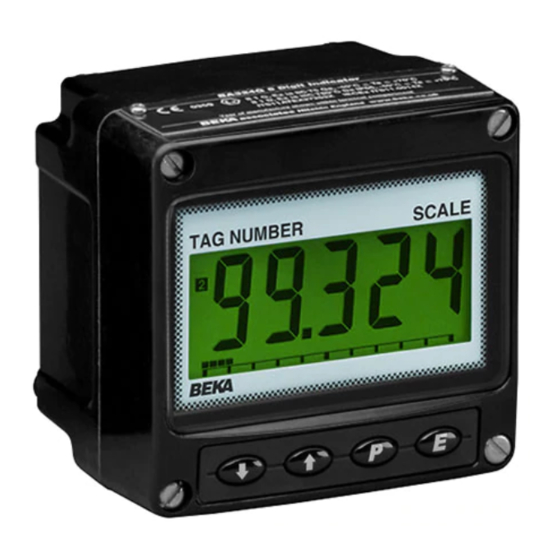
- Page 1 BA304NG & BA324NG Ex nA & Ex tc loop-powered field mounting indicators Issue 4 Issue: 4 November 2017...
-
Page 2: Table Of Contents
IECEx gas and dust certification Under and over-range Lineariser default configuration Appendix 3 ETL and cETL certification The BA304NG & BA324NG are CE marked to show compliance with the European Explosive Atmospheres Directive 2014/34/EU and the European EMC Directive 2014/30/EU... -
Page 3: Description
Each time a 4/20mA current is applied to the Model Display instrument, initialisation is performed during which all segments of the display are activated, after five BA304NG 4 digits 34mm high seconds the instrument displays the input current using the calibration information stored in the BA324NG 5 digits 29mm high and instrument memory. -
Page 4: Controls
Controls CERTIFICATION Both models are controlled and calibrated via four Both models have ATEX and IECEx gas and dust front panel push buttons. In the display mode i.e. certification. This section of the instruction manual when the indicator is displaying a process variable, describes ATEX gas certification. -
Page 5: 4/20Ma Input
2. Wiring must comply with Clause 9 of EN the ATEX and IECEx certification information and 60079-14 Electrical installation in hazardous BEKA associates name and location. areas. European certification information may also be shown. The instrument serial number and date of 3. -
Page 6: Remote Indication
Remote indication INSTALLATION The BA304NG and the BA324NG may be driven Location directly from a safe area instrument with a 4/20mA The BA304NG and BA324NG indicators are output to provide a remote display within a Zone 2 housed in robust IP66 glass reinforced polyester hazardous area. -
Page 7: Emc
To remove the scale card from an indicator carefully pull the transparent tab at the rear of the indicator assembly away from the indicator as Fig 4 BA304NG & BA324NG installation procedure shown in Fig 6a. Fig 6a Removing scale card... -
Page 8: Configuration And Calibration
All new indicators are supplied calibrated as requested at the time of ordering. If calibration is not requested, indicators will be supplied with the following default configuration: Default Configuration BA304NG BA324NG Access code CodE 0000 0000 Function FunC Linear... -
Page 9: Summary Of Configuration Functions
Summary of configuration functions Display Summary of function This section summarises each of the main configuration functions and includes a cross Function of ( push button C--P reference to a more detailed description. Fig 7 The indicator may be configured to illustrates the location of each function within the display the input current in milliamps, or configuration menu. -
Page 11: Indicator Function: Func
Indicator function: FunC Position of the decimal point: dP This configuration function defines the relationship A dummy decimal point can be positioned between between the indicator’s 4/20mA input current and any of the digits or it may be absent. To position the indicator’s display. -
Page 12: Calibration Using Internal Reference: 5Et
Calibration using internal reference: 5Et The indicator’s digital display at which the Using the 5Et function the indicator can be bargraph starts is defined by the bArLo sub- calibrated without the need to know the value of function which is selected by pressing the * the 4/20mA input current, or to disconnect the button followed by the ( button which will reveal indicator from the 4/20mA loop. -
Page 13: Security Code: Code
Underrange -9 . 9 . 9 . 9 -9 . 9 . 9 . 9 . 9 contact BEKA associates sales department if the Overrange 9 . 9 . 9 . 9 9 . 9 . 9 . 9 . 9 security code is lost. -
Page 14: Lineariser
LINEARISER Lineariser calibration using an external A sixteen segment, seventeen break-point (0 to 16) current source. This method allows direct calibration of the lineariser may be selected in the FunC section of the configuration menu. The position of each lineariser with an external current source and is the break-point is fully adjustable so that the slope of preferred method when traceability is required. -
Page 16: Lineariser Calibration Using Internal Reference
The delete break-point sub-function dEL operates required, using the * button select the new in exactly the same way as the Add sub-function highest break-point 2 : 2 and add the second described above. Once within the dEL sub-function additional break-point by operating the ( push each time the ( button is pressed a break-point is button which will result in a display of 2 : 3. -
Page 17: Under And Over-Range
The corresponding indicator display at each of the the defaults conditions are: break-points can now be defined using the di5P Indicator display sub-function. Using the & and * buttons select BA304NG BA324NG the di5P sub-function and press ( which will First break-point 0.00 0 : 1 reveal the starting point for the first break-point 0 : n, Second break-point 1 : 1 20mA 100.0... -
Page 18: Maintenance
Indicators which fail within the guarantee period terminals 1 & 3. power supply drop caused by all should be returned to BEKA associates or our local the instruments in agent. It is helpful if a brief description of the fault the loop. -
Page 19: Accessories
The backlight is loop powered by connecting it in identification. series with the indicator’s 4/20mA input as shown New BA304NG and BA324NG indicators are in Fig 11, which increases the maximum indicator supplied with a printed scale card showing the voltage drop from 1.2 to 5V. -
Page 20: Separately Powering The Backlight
9.2.2 Separately powering the backlight Alarms The optional backlight may also be powered from a CAUTION separate safe area power supply as shown in These alarms outputs should not be used Fig 12. for critical safety applications such as an emergency shut down system. -
Page 21: Solid State Output
Fig 15 shows a typical application in which a BA304NG or BA324NG indicator is displaying the output from a 2-wire transmitter in Zone 2. Alarm 1 is switching a solenoid valve in Zone 2 and alarm 2 is switching a sounder located in the safe area. -
Page 22: Configuration And Adjustment
Fig 16. The additional functions appear between the 5Et and the C--P functions for the Alarm enable EnbL BA304NG and between bAr and C--P for the Enables or disables the alarm without BA324NG indicator. For simplicity, Fig 16 only changing the alarm parameters. -
Page 24: Alarm Enable: Enbl
9.3.4 Alarm enable: EnbL This function allows each alarm to be enabled or To check or change the alarm output status, select disabled without altering any of the alarm no . nC from the alarm configuration menu and press parameters. To enable or disable the alarm select ( to reveal the setting. -
Page 25: 9.3.10 Alarm Silence Time: 5Il
9.3.10 Alarm silence time: 5iL This function is primarily intended for use in small This direct setpoint access menu is enabled and installations where the alarm output directly the separate security code entered from the AC5P operates an alarm annunciator such as a sounder function in the alarm configuration menu as shown or beacon. -
Page 26: Display Setpoints On Ba324Ng Bargraph
9.3.14 Displaying setpoints on BA324NG bargraph One of the selectable bargraph formats Alr5P allows a low or a high setpoint plus the displayed value to be represented, or a low and a high setpoint plus the displayed value to be represented by the bargraph as shown in Fig 18. -
Page 27: 9.4 Pipe Mounting Kit
BA304NG carbon loaded GRP enclosure. If the enclosure is or a BA324NG in a sealed panel enclosure. - Page 28 A1.3 Maintenance EN 60079-14 the indicators may be installed in: Ex tc protection does not permit live maintenance, but the BA304NG and BA324NG indicators may be Zone 22 explosive atmosphere in the form of calibrated in Zone 22 providing the instrument a cloud of combustible dust in air is enclosure is not opened.
- Page 29 IECEx is a global certification scheme for explosion For installations in the USA and Canada, the protected products which aims to harmonise BA304NG and BA324NG indicators have ETL and international certification standards. For additional cETL Ex nA and Ex tc approval, Control Number information about the IECEx certification scheme 4008610.
Need help?
Do you have a question about the BA304NG and is the answer not in the manual?
Questions and answers