
Related Manuals for BEKA BA304SG


Summary of Contents for BEKA BA304SG
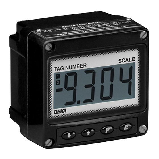
- Page 1 BA304SG & BA324SG Increased safety Ex eb and dust ignition protection by enclosure Ex tb loop-powered field mounting indicators Issue 2 Issue: 2 30th September 2020...
-
Page 2: Table Of Contents
Lineariser calibration using internal reference. 7.2.1 Example, Adding break-points to a new indicator. Under and over-range Lineariser default configuration The BA304SG and BA324SG are CE marked to show compliance with the European Explosive Atmospheres Directive 2014/34/EU and the European EMC Directive 2014/30/EU... -
Page 3: Description
BA324SG indicators should not be used in indicator will display the error message LPLo. intrinsically safe Ex i loops. The BA304SG and BA324SG may also be used as an alternative to a certified Ex nA indicator in Zone 2. -
Page 4: Controls
UK as BS EN 60079-7. While this button is pushed the indicator will display the input current To allow the BA304SG and BA324SG to be in mA, or as a percentage of the installed in Zone 1, both indicators incorporate an instrument span depending upon how encapsulated Ex mb assembly. -
Page 5: Zones, Gas Groups & T Rating
In European terms, compliance with the Low Voltage Directive ensures that this requirement is met. Like most flameproof indicators, the BA304SG and BA324SG Ex eb ib mb indicators... -
Page 6: System Design For Gas Hazardous Areas
Ex i or Ex nL. 4.1 Transmitter loops The BA304SG and BA324SG may be connected in series with almost any hazardous area Zone 1 or Zone 2 4/20mA loop. They can be configured and calibrated on-site to display a measured variable or control signal in engineering units. -
Page 7: Installation
INSTALLATION Installation Procedure Fig 6 illustrates instrument installation Location procedure for both models. BA304SG and BA324SG indicators have a robust enclosure that provides IP66 ingress A. Remove indicator assembly protection after a 7J impact. The thick armoured unscrewing the four captive 'A' screws. - Page 8 Fig 7 Dimensions of BA304SG and BA324SG. Fig 6 Installation procedure Fig 8 Terminal connections...
-
Page 9: Emc
Custom printed To replace the scale card carefully insert it into the scale cards are available from BEKA associates as slot on the right hand side of the input terminals as an accessory. -
Page 10: Configuration And Calibration
Enables the zero and span of the indicator to be adjusted without the need accurate input current Default Configuration BA304SG BA324SG disconnection from the 4/20mA loop. See section 6.6 Access code CodE 0000 0000 Function FunC... -
Page 12: Indicator Function: Func
Display Summary of function 6.2 Indicator function: FunC This configuration function defines the relationship Function of ( push button between the indicator’s 4/20mA input current and C--P the indicator’s display. Three alternatives are The indicator may be configured to display the input current in milliamps, or available: the input current as a percentage of the Standard linear relationship... -
Page 13: Position Of The Decimal Point: Dp
Position of the decimal point: dP Calibration using internal reference: 5Et A dummy decimal point can be positioned between Using the 5Et function the indicator can be any of the digits or it may be absent. To position calibrated without the need to know the value of the decimal point select dP from the menu and the 4/20mA input current, or to disconnect the press (. -
Page 14: Function Of The
Please bargraph scale flashing with a single contact BEKA associates sales department if the bargraph segment activated. security code is lost. Function of the ( push button: C--P 6.11 Reset to factory defaults: r5Et... -
Page 15: Lineariser Calibration Using An External Current Source
7. LINEARISER Lineariser calibration using an external A sixteen segment, seventeen break-point (0 to 16) current source. lineariser may be selected in the FunC section of This method allows direct calibration of the the configuration menu. The position of each lineariser with an external current source and is the preferred method when traceability is required. -
Page 17: Example, Adding Break-Points To A New Indicator
The delete break-point sub-function dEL operates required, using the * button select the new in exactly the same way as the Add sub-function highest break-point 2 : 2 and add the second described above. Once within the dEL sub- additional break-point by operating the ( push function each time the ( button is pressed a button which will result in a display of 2 : 3. -
Page 18: Under And Over-Range
Indicator display sub-function. Using the & and * buttons select BA304SG BA324SG the di5P sub-function and press ( which will reveal the starting point for the first break-point 0 : n,... - Page 19 Indicators which fail within the guarantee period No display Incorrect Check supply should be returned to BEKA associates or our local 0V between wiring or no voltage and voltage agent. It is helpful if a brief description of the fault terminals 1 &...
- Page 20 ACCESSORIES APPENDIX 1 9.1 Units of measurement & instrument identification. Dust Certification New indicators are supplied with a printed scale card showing the units of measurement and tag information specified when the instrument was A1.0 Ex tb dust certification ordered. If this information was not supplied a In addition to IECEx and ATEX certification blank scale card will be supplied which can easily...
- Page 21 A1.2 Installation and maintenance The installation requirement described in this manual for use in potentially explosive gas atmospheres also apply when the indicators are installed potentially combustible dust atmosphere. The instrument enclosure should only be opened when the indicator is de-energised and dust can not enter the instrument enclosure.
Need help?
Do you have a question about the BA304SG and is the answer not in the manual?
Questions and answers