
Related Manuals for BEKA BA304NE


Summary of Contents for BEKA BA304NE
- Page 1 BA304NE & BA324NE Type n loop-powered field mounting indicators Issue 2 Issue: 2 December 2011...
-
Page 2: Table Of Contents
7.2 Lineariser calibration using internal reference. 7.3 Lineariser error message 7.4 Under and over-range 7.5 Lineariser default configuration The BA304NE & BA324NE are CE marked to show compliance with the European Explosive Atmospheres Directive 94/9/EC and the European EMC Directive 2004/108/EC... -
Page 3: Description
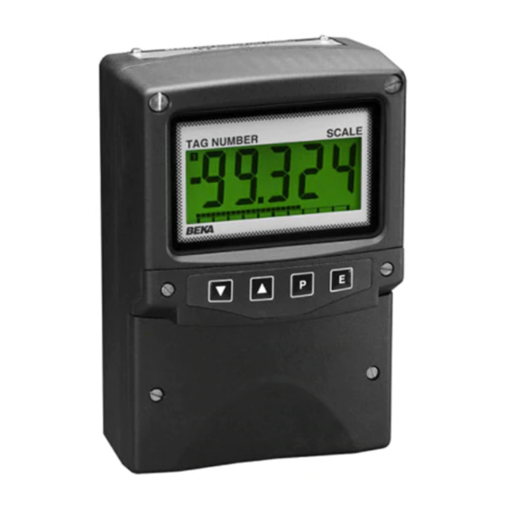
Each time a 4/20mA current is applied to the instrument, initialisation is performed during which Model Display all segments of the display are activated, after five BA304NE 4 digits 15mm high seconds the instrument displays the input current using the calibration information stored in the BA324NE 5 digits 11mm high and 31 segment instrument memory. -
Page 4: Controls
2.1 Controls 3. CERTIFICATION The indicators are controlled and calibrated via Both models have ATEX and IECEx gas and dust four push button switches located behind the certification. This section of the instruction manual instrument control cover, or as an option on the describes ATEX gas certification. -
Page 5: 4/20Ma Input
The certification label is fitted in a recess on the top outer surface of the instrument enclosure. It shows the ATEX certification information and BEKA associates' name and location. European certification information may also be shown. The instrument serial number and date of manufacture are recorded on a separate label inside the terminal compartment. -
Page 6: Remote Indication
4.2 Remote indication The BA304NE and the BA324NE may be driven directly from a safe area instrument with a 4/20mA output to provide a remote display within a Zone 2 hazardous area. There are four design requirements: 1. The current flowing in the 4/20mA loop, must not exceed 100mA in normal operation. -
Page 7: Installation
5. INSTALLATION 5.1 Location The BA304NE and BA324NE indicators are housed in robust IP66 glass reinforced polyester (GRP) enclosures incorporating an armoured glass window and stainless steel fittings making them suitable for exterior mounting in most industrial installations, including off-shore and waste water treatment. -
Page 8: Configuration And Calibration
4/20mA loop. following default configuration: See section 6.6 Default Configuration 'bAr' Bargraph format and claibration BA304NE BA324NE Only the BA324NE has a bargraph Access code ‘CodE’ 0000 0000 The bargraph may be conditioned to Function ‘FunC’... - Page 10 Display Summary of function 6.2 Indicator function: ‘FunC’ This configuration function defines the relationship 'C - - P' Function of P push button between the indicator’s 4/20mA input current and The indicator may be configured to the indicator’s display. Three alternatives are display the input current in milliamps, or available: the input current as a percentage of the...
-
Page 11: Calibration Using An External
6.4 Position of the decimal point: ‘dP’ 6.6 Calibration using internal reference: A dummy decimal point can be positioned between ‘SEt’ any of the digits or it may be absent. To position Using the ‘SEt’ function the indicator can be the decimal point select 'dP' from the menu and calibrated without the need to know the value of press P. -
Page 12: Function Of The P Push Button
E twice will return the display indicator is returned to the display mode. to the ‘bAr’ prompt in the configuration menu. Please contact BEKA associates sales department Note: ‘bArLo’ must be set lower than ‘bArHi’, if the security code is lost. -
Page 13: Lineariser
variable to be displayed. e.g. the output from a 7. LINEARISER A sixteen segment, seventeen breakpoint (0 to 16) level sensor in an irregular tank may be displayed lineariser may be selected in the ‘FunC’ section of in linear volumetric units by filling the tank with the configuration menu. -
Page 15: Lineariser Calibration Using Internal Reference
When the required number of linearising break- 'dEL' Remove a break-point points have been entered, return Removes the displayed break-point linearisation sub-menu by pressing E. and joins the preceding segment to the indicator will display the 'Add' or 'dEL' prompt following segment with a straight line. -
Page 16: Lineariser Error Message
▲ and ▼ in section 6.11, the defaults conditions are: buttons. When the required break-point has been selected press P and set the indicator input current BA304NE BA324NE First break-point 4mA 0.00 at this break-point. Repeat this procedure until the Second break-point 20mA 100.0... -
Page 17: Fault Finding During Commissioning
8.5 Guarantee noisy. 4/20mA power Indicators which fail within the guarantee period supply and/or should be returned to BEKA associates or our local decrease indicator agent. It is helpful if a brief description of the fault resolution. Unable to enter... -
Page 18: External Keypad
Fig 9 illustrates the Both the BA304NE and the BA324NE indicators conditions available and shows which are fail safe. are fitted with a blank escutcheon around the liquid crystal display. This can be supplied printed with... -
Page 19: Solid State Output
200mA. considered adequate. Fig 11 shows a typical application in which a BA304NE or BA324NE indicator is displaying the output from a 2-wire transmitter in Zone 2. Alarm 1 is switching a solenoid valve in Zone 2 and alarm 2 is switching a sounder located in the safe area. -
Page 21: Configuration And Adjustment
Fig 12. The additional functions appear between the ‘SEt’ and the ‘C- - P’ functions for the 'EnbL’ Alarm enable BA304NE and between ‘bAr’ and ‘C- -P’ for the Enables or disables the alarm without BA324NE indicator. For simplicity, Fig 12 only changing the alarm parameters. - Page 22 To check or change the alarm output status, select 9.3.4 Alarm enable: ‘EnbL’ This function allows each alarm to be enabled or 'no.nC' from the alarm configuration menu and disabled without altering any of the alarm press P to reveal the setting. The function may be parameters.
-
Page 23: Access Setpoint In Display
indicator is in the display mode is provided by a 9.3.10 Alarm silence time: SiL This function is primarily intended for use in small separate security code. installations where the alarm output directly operates an alarm annunciator such as a sounder This direct setpoint access menu is enabled and or beacon. -
Page 24: Displaying Setpoints On Ba324Ne Bargraph
9.3.14 Displaying setpoints on BA324NE bargraph One of the selectable bargraph formats ‘AlrSP’ allows a low or a high setpoint plus the displayed value to be represented, or a low and a high setpoint plus the displayed value to be represented by the bargraph as shown in Fig 14. -
Page 25: Display Backlight
9.4 Display backlight 9.4.2 Separately powering the backlight The BA304NE and BA324NE loop powered The optional backlight may also be powered from a indicators can be supplied with a factory fitted separate safe area power supply as shown in backlight that may be loop or separately powered. -
Page 26: Pipe Mounting Kits
9.5 Pipe mounting kits Two pipe mounting kits are available for securing the BA304NE and BA324NE to a horizontal or vertical pipe. BA392D Stainless steel bracket secured by two worm drive hose clips. Will clamp to any vertical or horizontal pipe with an outside diameter between 60 and 80mm. - Page 27 Zone 22 combustible dust applications. described in the main section of this instruction indicator should be located where the minimum manual, the BA304NE and the BA324NE also amount of dust will accumulate on the enclosure have ATEX Ex tc certification, allowing installion in and the installation should be as specified in this Zone 22 combustible dust atmospheres.
- Page 28 BEKA associate certificates, please visit www.iecex.com A2.1 IECEx Certificate of Conformity The BA304NE and the BA324NE loop powered indicators and the optional accessories have been issued with an IECEx Certificate of Conformity number IECEx ITS 11.0016 that specifies the...
Need help?
Do you have a question about the BA304NE and is the answer not in the manual?
Questions and answers