Stanley MC521 Pro Installation And Operation Manual
Controller slide door
Hide thumbs
Also See for MC521 Pro:
- Installation and operation manual (56 pages) ,
- Quick reference manual (20 pages) ,
- Installation and operation manual (30 pages)
Table of Contents
Advertisement
Quick Links
- 1 Installing the Mc521 Pro Controller
- 2 Tuning in the Mc521 Pro Controller Using Pushbuttons
- 3 Attachment 1 - Mc521 Pro Controls and Indicators
- 4 Attachment 2 - Mc521 Pro System Wiring Diagram
- 5 Attachment 5 - Handheld Device Troubleshooting Aid
- 6 Attachment 7 - Mc521 Pro Troubleshooting Aid
- Download this manual
Prepared by: Jeff Bonas
CN: _________
Engineering Document Number: ________
Product Information
Bifold
Slide
Tech Tip Classification
Adjustment
Installation
Release Action
Level 1 - Does not impact maintenance or operation of door. (Only Safety/Liability and Engineering need to sign.)
Level 2 - Full sign off required.
Release Information (initial and date)
Safety/Liability
_________________________
Engineering
_________________________
Technical Support _________________________
Field Operations
_________________________
Quality
_________________________
Cover Page
MC521 PRO CONTROLLER
Installation and Operation Manual
Engineer: Tony Ranaudo, Len Pursell
RDW: ________
Swing
Class 2
Customer Complaints
Clarifications
If you have any questions concerning this procedure, contact
Access Technologies Technical Support, at 1-800-422-6489 Option 3.
TECH TIP
SLIDE DOOR
Reference Tech Tip: ________
Summary Information
Accessories
Controls
FAQs
Service
Tech Tip: TT170727
Operators / Drives
Panels / Hardware
Retrofit/Upgrade Instructions
Design Change Description
Technical News July 27, 2017
Sensors
Tech Tip: TTxxxxxx
Advertisement
Table of Contents
Troubleshooting

Related Manuals for Stanley MC521 Pro


Summary of Contents for Stanley MC521 Pro
- Page 1 Technical News July 27, 2017 TECH TIP MC521 PRO CONTROLLER SLIDE DOOR Installation and Operation Manual Prepared by: Jeff Bonas Engineer: Tony Ranaudo, Len Pursell Tech Tip: TT170727 CN: _________ RDW: ________ Reference Tech Tip: ________ Engineering Document Number: ________...
- Page 2 SLIDE DOOR Installation and Operation Manual Attached is the revised MC521 Pro Controller Manual: MC521 Pro Controller Installation and Operation Manual (204066) Rev. F, for automatic sliding doors) Included in the revised manuals are the following: ...
- Page 3 Stanley Part Number 204066 REV F 12.2016 Copyright 2016, Stanley Access Technologies, LLC. Prohibition on Copying: Any unauthorized reproduction, disclosure or distribution of copies by any person of any portion of this work may be a violation of copyright law of the United States of America and other countries, could result in the awarding of statutory damages of up to $250,000 (17 USC 504) for infringement, and may result in further civil and criminal penalties.
-
Page 4: Table Of Contents
Controller. It includes instructions for Dura-Glide™ 2000/3000, 5200/5300, Dura-Guard™, Dura-Storm™, and Dura- Max™ 5400-Series, Automatic Slide door systems. On Dura-Glide sliding doors, the MC521 Pro Controller replaces the MC521 or both the microprocessor control box and the interface board on older models. The door activation devices (SU-100 motion sensors, carpets, push plates, etc.), lock, function switch, doorway holding beams, and door position switches previously connected to the... -
Page 5: Prerequisites
INSTALLATION INSTRUCTIONS Installing the MC521 Pro Controller NOTE : This manual covers new door installations in which the MC521 Pro is factory-installed and wired. WIRING INSTRUCTIONS Evaluating Power Requirements • ENSURE power source is a dedicated 115 VAC, 50/60 Hz source with 20A circuit rating. If four operators are used, the source should have a 30A rating. -
Page 6: Connecting Main Power Wiring
• Header cover opens and closes without interference. Connecting Accessories (As Applicable) Refer to Attachments 2 and 3, and CONNECT any of the following subsystems to the MC521 Pro Controller: • Function switch (rotary, rocker and “POWER” switch wiring). • Stanguard threshold sensor. -
Page 7: Tuning In The Mc521 Pro Controller Using A Handheld Device
: The following steps provide instructions for tuning the MC521 Pro Controller using a handheld device. MC521 application software is required. Connect the handheld device to the MC521 Pro Controller, turn on header POWER switch, and perform the following steps. - Page 8 MC521 PRO Control Box Step 4 : Select applicable Switch Type Motor Step 3 : Select Duraglide , and Setup Motor Handing Step 6 : Configure additional settings and press Step 5 : If additional configuration is needed, after each setting has been...
- Page 9 Handheld by pressing Operate **After performing Step 9 or 10, the door opens fully, delays and then closes fully. The MC521 Pro displays 00 when FIS is completed.** Step 11 : If the door is not operating correctly...
- Page 10 MC521 PRO Control Box Step 15 : Press lto view all Step 16: Review the information on the Summary current settings. listing. Summary Step 17 : Sensor Monitoring On displayed when configured for monitored sensors. Document # 204066 REV F • www.stanleyaccess.com • 1.800.7.ACCESS...
-
Page 11: Tuning In The Mc521 Pro Controller Using Pushbuttons
MC521 PRO Control Box Tuning In the MC521 Pro Controller Using the Controller Pushbuttons NOTE: 1. To change the INDEX Hold switch while pressing to get to desired ENTER UP or DOWN INDEX 2. To change a VALUE Unlock the keypad by setting index 99 to value 00. - Page 12 : Switch to , momentarily, then Function Switch OPEN CLOSED/ . The door opens fully, delays and then closes LOCKED fully. The MC521 Pro displays A2 when FIS is completed. Lock keypad. Final Tune in. Table 2. Index List Index Description 00-89 Settings Values, see Table 3.
- Page 13 00 = Off (Delay Egress), 01 = 15 sec. delay, 02 = 30 sec. delay. 00 - Monitored 2 Sensors - Threshold Zone Control (The threshold zone is enabled and disabled by the MC521 Pro). 01 - Monitored 4 Sensors - Threshold Zone Control (The threshold zone is enabled and disabled by the MC521 Pro).
- Page 14 MC521 PRO Control Box Table 3. Settings (continued) Open Stop. Distance (1/8” increments) from full open the door will stop. Access Control Pro. 00 = off, 01 = on. Press Time, 00 = least amount, 03 = most amount of pressing.
-
Page 15: Final Tune-In Adjustments
Door State is in Recycle or Obstruction While Closing Door State is in Close Press : If the current status code is “Normal operation—All OK”, the MC521 Pro will show the current door state. NOTE Otherwise, the MC521 Pro alternates between showing the current status code and the door state. -
Page 16: Spare Parts List
MC521 PRO Control Box Table 6. Spare Parts List Description Part Number MC521 Pro Controller, includes 4 terminal blocks 314117 MC521 Pro Controller Manual 204066 Harness, Rocker Switch to Control Box, 98 inches 414098 Harness, Rocker Switch to Control Box, 180 inches... -
Page 17: Attachments
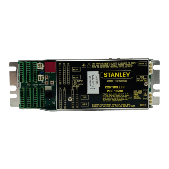
MC521 PRO Control Box Attachment 1 MC521 Pro Controls and Indicators (Sheet 1 of 2) SEE DETAIL A JP200 DETAIL A NOTE: See next page for indicators and descriptions 1.800.7.ACCESS • www.stanleyaccess.com • Document # 204066 REV F... - Page 18 MC521 PRO Control Box Attachment 1 MC521 Pro Controls and Indicators (Sheet 2 of 2) ITEM CONTROL/INDICATOR DESCRIPTION Motor 2 Connector P402 Motor No. 2 connector. Connection point for incoming line, neutral, and common Power Connector J500 power wiring. Fuse F500...
-
Page 19: Attachment 2 - Mc521 Pro System Wiring Diagram
MC521 PRO Control Box Attachment 2 MC521 Pro System Wiring Diagram (Sheet 1 of 10) 1.800.7.ACCESS • www.stanleyaccess.com • Document # 204066 REV F... - Page 20 MC521 PRO Control Box Attachment 2 MC521 Pro System Wiring Diagram (Sheet 2 of 10) Document # 204066 REV F • www.stanleyaccess.com • 1.800.7.ACCESS...
- Page 21 MC521 PRO Control Box Attachment 2 MC521 Pro System Wiring Diagram (Sheet 3 of 10) 1.800.7.ACCESS • www.stanleyaccess.com • Document # 204066 REV F...
- Page 22 MC521 PRO Control Box Attachment 2 MC521 Pro System Wiring Diagram (Sheet 4 of 10) Document # 204066 REV F • www.stanleyaccess.com • 1.800.7.ACCESS...
- Page 23 MC521 PRO Control Box Attachment 2 MC521 Pro System Wiring Diagram (Sheet 4 of 10, continued) 1.800.7.ACCESS • www.stanleyaccess.com • Document # 204066 REV F...
- Page 24 MC521 PRO Control Box Attachment 2 MC521 Pro System Wiring Diagram (Sheet 5 of 10) COLOR DUAL HOLDING BEAM WIRING OUTPUT UPPER RECEIVER (-) UPPER RECEIVER OUTPUT LOWER RECEIVER (-) LOWER RECEIVER TRANSMITTER CONTROL LOWER AND UPPER NO CONNECTION NO CONNECTION...
- Page 25 MC521 Pro System Wiring Diagram (Sheet 6 of 10)) Program the OS-12 CT set to “D” - Active High / N.C. On the MC521 Pro set Index 20 to Value 01 (Hold Beam Pro). 1.800.7.ACCESS • www.stanleyaccess.com • Document # 204066 REV F...
- Page 26 MC521 PRO Control Box Attachment 2 MC521 Pro System Wiring Diagram (Sheet 7 of 10) COLOR PHOTO BEAM PRO BREAKOUT BEAM JUMPER FROM TB3-5 JUMPER FROM TB3-6 NO CONNECTION NO CONNECTION JUMPER FROM TB3-1, (+) RECEIVER AND TRANSMITTER JUMPER FROM TB3-2, (-) RECIEVER AND TRANSMITTERS\...
- Page 27 MC521 PRO Control Box Attachment 2 MC521 Pro System Wiring Diagram (Sheet 8 of 10) X Zone ST Key DIP Switch settings: 10 and 11 DOWN; 12, 14 and 15 UP. MC521 Pro Remove JP200. Set index 19 to Value = 00 (Sensor Monitoring with Threshold Control).
- Page 28 MC521 PRO Control Box Attachment 2 MC521 Pro System Wiring Diagram (Sheet 9 of 10) X Zone ST Key DIP Switch settings: 10 and 11 DOWN; 12, 14 and 15 UP. MC521 Pro Remove JP200. Set index 19 to Value = 01 (Monitored 4 Sensors - Threshold Zone Control).
- Page 29 MC521 PRO Control Box Attachment 2 MC521 Pro System Wiring Diagram (Sheet 10 of 10) HR100 ST Recommended DIP Switch settings: DIP Switch X: (2, 3, 4, 5, 6, 7 and 8 = UP) (1=DOWN). DIP Switch Y: (1, 2, and 4 = UP) (5 and 6 = DOWN).
-
Page 30: Attachment 3 - Mc521 Pro Terminal Block Connections Tb1-Tb7
MC521 PRO Control Box Attachment 3 MC521 Pro Terminal Block Connections -- TB1 through TB7 (Sheet 1 of 1) Document # 204066 REV F • www.stanleyaccess.com • 1.800.7.ACCESS... - Page 31 MC521 PRO Control Box Attachment 4 ANSI/BHMA and UL Compliance Requirements for Sliding Doors (Sheet 1 of 2) Final adjustment and proper operation of the door system must be and shall be performed in the field. NOTE : These instructions are for informational purposes and do not substitute for review against the current revision of the referenced standards.
- Page 32 MC521 PRO Control Box Attachment 4 ANSI/BHMA and UL Compliance Requirements for Sliding Doors (Sheet 2 of 2) To ensure that a sliding door operates in accordance with UL 325 entrapment protection criteria the following must be established: • Manual opening force (sliding doors without breakout) or breakout force with power on or off must be less then 50 lbf (222.4 N).
-
Page 33: Attachment 5 - Handheld Device Troubleshooting Aid
MC521 PRO Control Box Attachment 5 -- Handheld Device Troubleshooting Aid (Sheet 1 of 1) Terminal and Pin Description State TB1-8 Solenoid Lock Output Dark = Unlocked w/o PCB, fail secure Dark = Unlocked w/o PCB, fail safe Dark = Locked... -
Page 34: Attachment 6 - Handheld Device Troubleshooting Screen Descriptions
MC521 PRO Control Box Attachment 6 Handheld Device Troubleshooting Screen Descriptions (Sheet 1 of 2) TB1-8 = Solenoid Lock Output TB2-1 = Hold Open Function Switch Input TB2-3 = Automatic Function Switch Input TB2-5 = Enter/One Way Function Switch Input... - Page 35 (Sheet 2 of 2) Output Control Mode The Output Control allows the user to run the MC521 Pro Control Box in a debug mode. The Output Control is located on the MC521 Troubleshooting Screen. The MC521 Pro firmware needs to be above 7.97 for the Toolbox to have Output Control Mode functionality.
-
Page 36: Attachment 7 - Mc521 Pro Troubleshooting Aid
Door does not close fully (1-2”open) Increase close press time (index 25). Door motion is not the same as the MC521 for Parameters value for the MC521 Pro are not the same as the same settings MC521. Refer to Table 3. -
Page 37: Attachment 8 - Recommended Values For Different/Weights Types Of Slide Door
MC521 PRO Control Box Attachment 8 Recommended Values for Different/Weights Types of Slide Door Index Description Slide Doors 125 LB 350 LB 100 LB 600 LB Dura-Max Single Motor Single Motor Single Motor Double Diamond Single Slide Bi-Part - LPH Bi-part or Equiv. -
Page 38: Attachment 9 - Fine Tuning Slide Doors
MC521 PRO Control Box Attachment 9 Fine Tuning Slide Doors (Sheet 1 of 2) Tuning the Stanley Automatic Door Match your actual door to one from the list of doors described in the attachment. Start by installing these settings. Use the guide below to make adjustments to these settings. - Page 39 MC521 PRO Control Box Attachment 9 Fine Tuning Slide Doors (Sheet 2 of 2) Tuning the Stanley Automatic Door (Continued). Match your actual door to one from the list of doors described in the attachment. Start by installing these settings. Use the guide below to make adjustments to these settings.
- Page 40 Stanley Access Technologies 65 Scott Swamp Road Farmington, CT 06032 Document # 204066 REV F • www.stanleyaccess.com • 1.800.7.ACCESS...
Need help?
Do you have a question about the MC521 Pro and is the answer not in the manual?
Questions and answers