Advertisement
Table of Contents
- 1 Table of Contents
- 2 Introduction
- 3 EX5500 Controller Applications and Industry Examples
- 4 EX5500 Controller Features
- 5 EX5500 LED Status Indicators
- 6 Network and Power Connections to EX5500
- 7 Chaining the EX5500 Controllers
- 8 Resetting the EX5500 Controller IP Address
- 9 Configuring the EX5500 Controller
- 10 Configuring the Controller Via Cisco MSE
- 11 Mounting the Controller and External LF Antenna
- 12 Mounting the Controller or External LF Using the Exciter Mounting Clip
- 13 EX5500 and Accessories Model Numbers
- 14 EX5500 Specifications
- Download this manual
Advertisement
Table of Contents

Related Manuals for Stanley EX5500


Summary of Contents for Stanley EX5500
- Page 1 EX5500 Controller Installation & Configuration Guide 0981-029 Rev A...
- Page 2 This document is confidential and proprietary to Stanley Healthcare and is not to be distributed to any persons other than licensed AeroScout Visibility System users or other persons appointed in writing by Stanley Healthcare.
-
Page 3: Table Of Contents
Table of Contents Introduction ......................... 4 EX5500 Controller Applications and Industry Examples ..........5 EX5500 Controller Features ....................6 EX5500 LED Status Indicators ..................7 Network and Power Connections to EX5500 ............... 10 Chaining the EX5500 Controllers ................... 13 Resetting the EX5500 Controller IP Address ..............15 Configuring the EX5500 Controller ................ -
Page 4: Introduction
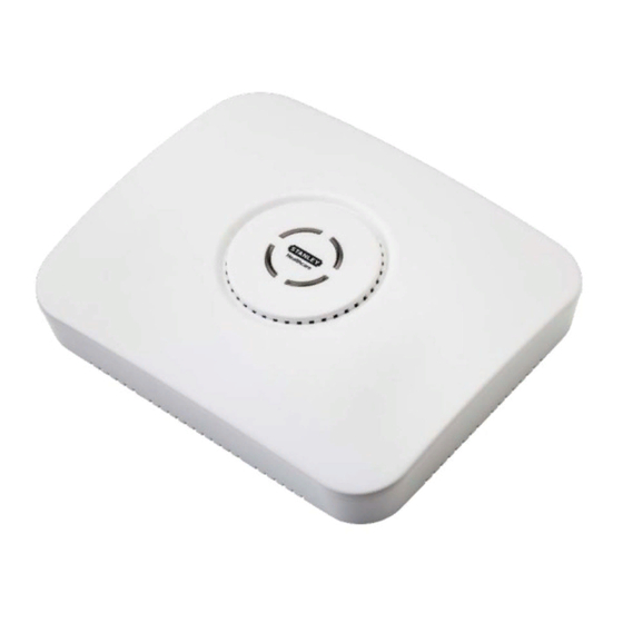
The EX5500 Controller provides sophisticated RFID detection, monitoring, and control capabilities. The EX5500 Controller triggers Hugs Tags as they pass through an Egress or as they approach the Controller. Tags in turn transmit a message to either the Location Receivers or to compatible Access Points within range. -
Page 5: Ex5500 Controller Applications And Industry Examples
NICU. Mission Critical Applications The EX5500 Controller can work in an off-line mode, enabling it to function as a security application even when the network is down and communication with... -
Page 6: Ex5500 Controller Features
EX5500 Controller Features RFID detection of Stanley Healthcare Tags The EX5500 Controller triggers Tags to transmit as they pass through a defined area, within a range of up to 6.5 meters (21.3 feet). This is typically enough to cover door or gate areas. -
Page 7: Ex5500 Led Status Indicators
In the offline mode however, remote configuration and monitoring is not available. EX5500 LED Status Indicators The EX5500 has a single LED that changes color based on the Controller status as follows: Constant Green: The Controller is on and working correctly. - Page 8 EX5500 Controller Installation & Configuration Guide EX5500 Controller Connector Panel The EX5500 Controller has five connectors and two relay switches on the connector panel. Figure 4: Stanley Healthcare EX5500 Connector Wiring Figure 5: Stanley Healthcare EX5500 Connectors...
- Page 9 Ethernet cable connection to the LAN, the network cable is attached here. Permanent connection to a wired network is not mandatory. However, you must have a wired connection to configure the EX5500 Controller. Some monitoring functions are not available if the Controller is not wired. This connection is also used for Power over Ethernet (PoE, 802.3af).
-
Page 10: Network And Power Connections To Ex5500
EX5500s can be used as standalone devices that function connected to a independently without any network connection. In this network case, you only need to connect the EX5500 to the power supply. Using System Manager, set the device as “not connected to the network."... - Page 11 If your network has a Power-over-Ethernet infrastructure, you can connect a CAT-5 Ethernet cable from the PoE switch to the Controller’s LAN connector. This supplies both the power and the network connection. PoE standard 802.3af class 0 allows power for a single EX5500 Controller Note When using PoE with the other chained Exciters, a PoE connection must be made to every second Exciter in the chain.
- Page 12 These adaptors convert 110 VAC or 220 VAC to 48 VDC. Figure 7: 110/220 VAC to 48 VDC Adaptor The adaptor is connected to the EX5500 Controller’s power jack. The network must be connected separately to the EX5500 Controller’s LAN connector. This adaptor is most commonly used for chained Exciters.
-
Page 13: Chaining The Ex5500 Controllers
Figure 8: EX5500 Chaining Using a Power Adaptor EX5500 Chain Connection Up to 4 Exciters can be connected to the EX5500 in a chain, as follows: The first Exciter in the chain, directly connected to the LAN, is designated the “Master”. - Page 14 EX5500 Controller Installation & Configuration Guide The Master Exciter is connected to the first Slave Exciter as follows: Master Chain OUT to Slave Chain IN. Slave Exciters are then connected as follows: Slave OUT to Slave IN. The Termination Switch of the Master Exciter and the last Slave Exciter in the chain must be set to On (o-o).
-
Page 15: Resetting The Ex5500 Controller Ip Address
• Checkbox Resetting the EX5500 Controller IP Address You can reset the EX5500 Controller’s IP address to the factory default value. The default IP address is 192.168.1.178. Press the IP Reset button with a ballpoint pen for 5 second. •... -
Page 16: Configuring The Ex5500 Controller
The configuration settings consist of device installation and network definitions. Configuring the EX5500 Controller via System Manager The EX5500 Controller requires settings in the System Parameters and the Exciter Properties dialog boxes to be configured. System Manager can automatically detect the Exciter Model. - Page 17 Set the Check Interval. Exciter Properties Add the EX5500 Controller to System Manager. On the map double-click the EX5500 Controller. The Exciter Properties dialog box opens. In the Exciter Properties dialog box General Module select the Settings tab. a. Enable the Internal LF Exciter.
- Page 18 EX5500 Controller Installation & Configuration Guide Select the Internal LF Exciter Module. a. Select the Tag Reactions tab. b. Ensure the Send leaving Exciters range notification option is unavailable. c. Select the Tag Transmission Parameters tab. d. Tag Repetitions of an Exciter, select the Number of Repetitions option.
- Page 19 EX5500 Controller Installation & Configuration Guide Select the Advanced Tab g. Ensure the Make Tag Blink option is set to Exclude … Select the Controller Module. Configure as follows:...
- Page 20 EX5500 Controller Installation & Configuration Guide Controller Mode a. Select Security solutions for Hugs tags only. Select Chokepoint control for other deployments. Relays and Sensors a. Select the Normally state of Relay 1 and Relay 2 as either Active or Inactive.
- Page 21 Align the EX5500 Controller position according to the required coverage area. If you wish to define an EX5500 Controller as an offline Exciter, you must define the Controller as disconnected from network in the Exciter Properties dialog box, approve the settings and then disconnect the Exciter from the network.
-
Page 22: Configuring The Controller Via Cisco Mse
EX5500 Controller Installation & Configuration Guide Configuring the Controller via Cisco MSE Follow this procedure: Open the WCS and select Configure, Chokepoints. Select Add Chokepoint. Enter the MAC address, Name and Static IP Address. Click Save. Select Monitor, Maps and then the relevant campus, building and floor. - Page 23 EX5500 Controller Installation & Configuration Guide Select Add Chokepoint and click Go. Check the relevant Exciter and click OK. You are returned to the relevant floor area. Locate the added Exciter on the map and click Save. Select Services, Synchronize Services and synchronize the relevant MSE.
-
Page 24: Mounting The Controller And External Lf Antenna
Figure 9: Controller mounted on a Floating Ceilings Mounting the Controller on a Wall Mount the Exciter with the Stanley Healthcare logo facing up. Attach the Controller to the wall using the two screw mounts on the •... -
Page 25: Mounting The Controller Or External Lf Using The Exciter Mounting Clip
EX5500 Controller Installation & Configuration Guide Mounting the External LF Antenna on a Wall Attach the External LF Antenna to the wall using the two screw mounts • located on the bottom casing. Mounting the Controller or External LF using the... - Page 26 EX5500 Controller Installation & Configuration Guide b. Screw them into the Mounting clip. The screw heads should remain 2-3cm below the ceiling tile. c. Attach the Controller or LF Antenna using the two screw mounts on the bottom casing. Figure 13: External LF Antenna mounted using the Exciter Mounting Clip...
-
Page 27: Ex5500 And Accessories Model Numbers
EX5500 Controller Installation & Configuration Guide EX5500 and Accessories Model Numbers Product Description EX5500 Controller EX-5500 EX5500 Controller. Includes 48V DC input, Ethernet and PoE interface EX5500 Power ADP-047 AC/DC adaptor 45W 48V/1.0A 90-264VAC. Supply PoE Injector ADP-030-U 110/220 VAC to 48 VDC PoE Single-Port... -
Page 28: Ex5500 Specifications
EX5500 Controller Installation & Configuration Guide EX5500 Specifications Physical and Mechanical Dimensions: 192mm X 242mm X 61mm (6.1in x 7.1in x 1.8in) • Weight: 450g (16oz) • Housing: Polycarbonate and ABS • Range Adjustable from 0.5m (20 in) up to 6.5m (21.3ft) in intervals of 0.5m (20 in) •... - Page 29 EX5500 Controller Installation & Configuration Guide FCC Compliance Statement This device has been tested and found to comply with the limits for a Class B digital device, pursuant to Part 15 of the FCC Rules. These limits are designed to provide reasonable protection against harmful interference in residential installations.
- Page 30 Operations & Workflow and Supply Chain & Asset Management. These integrated solutions are complemented by consulting, training and Transformational Lean™ process reengineering. Stanley Healthcare is proud to be part of Stanley Black & Decker, Inc. For more information, visit www.StanleyHealthcare.com.
Need help?
Do you have a question about the EX5500 and is the answer not in the manual?
Questions and answers