Stanley MC521 PRO Installation And Operation Manual
Control box swing and bifold doors
Hide thumbs
Also See for MC521 PRO:
- Installation and operation manual (40 pages) ,
- Quick reference manual (20 pages) ,
- Installation and operation manual (30 pages)
Table of Contents
Advertisement
Prepared by: Jeff Bonas
CN: _________
Engineering Document Number: ________
Product Information
Bifold
Slide
Tech Tip Classification
Adjustment
Installation
Release Action
Level 1 - Does not impact maintenance or operation of door. (Only Safety/Liability and Engineering need to sign.)
Level 2 - Full sign off required.
Release Information (initial and date)
Safety/Liability
_________________________
Engineering
_________________________
Technical Support _________________________
Field Operations
_________________________
Quality
_________________________
Cover Page
MC521 PRO CONTROL BOX
SWING AND BIFOLD DOORS
Installation and Operation Manual
Engineer: Tony Ranaudo, Len Pursell
RDW: ________
Swing
Class 2
Customer Complaints
Clarifications
If you have any questions concerning this procedure, contact
Access Technologies Technical Support, at 1-800-422-6489 Option 3.
TECH TIP
Reference Tech Tip: ________
Summary Information
Accessories
Controls
FAQs
Service
Tech Tip: TT170728
Operators / Drives
Panels / Hardware
Retrofit/Upgrade Instructions
Design Change Description
Technical News July 28, 2017
Sensors
Tech Tip: TT170728
Advertisement
Table of Contents

Related Manuals for Stanley MC521 PRO


Summary of Contents for Stanley MC521 PRO
- Page 1 Technical News July 28, 2017 TECH TIP MC521 PRO CONTROL BOX SWING AND BIFOLD DOORS Installation and Operation Manual Prepared by: Jeff Bonas Engineer: Tony Ranaudo, Len Pursell Tech Tip: TT170728 CN: _________ RDW: ________ Reference Tech Tip: ________...
- Page 2 Attached is the revised MC521 Pro Controller Manual: MC521 Pro Control Box for Swing and Bifold Doors Installation and Operation Manual (204090 rev. D) Included in the revised manuals are the following: Settings for Monitored Presence Sensors ...
- Page 3 Stanley Part Number 204090 REV D 03.2017 Copyright 2017 Stanley Access Technologies, LLC. Prohibition on Copying: Any unauthorized reproduction, disclosure or distribution of copies by any person of any portion of this work may be a violation of copyright law of the United States of America and other countries, could result in the awarding of statutory damages of up to $250,000 (17 USC 504) for infringement, and may result in further civil and criminal penalties.
-
Page 4: Table Of Contents
This manual provides abbreviated descriptive information, wiring instructions, and tune-in instructions for the MC521 PRO controller used with Magic-Swing™, Magic-Force™, and Bifold operators. The manual is intended as a quick-reference guide. Attachment 7 illustrates the MC52I PRO controller controls and indicators. -
Page 5: Features And Functions
Magic-Touch™: A feature that allows the door to be actuated by a slight manual movement of the door-without the need for an approach sensor. The MC521 PRO control box controls the Magic-Touch hold-open time delay. Magic-Touch can be used with press plates or a radio control system, providing the system with two separate time delays. -
Page 6: Wiring Instructions
MC521 PRO Control Box WIRING INSTRUCTIONS Evaluate Power Requirements EVALUATE door system power requirements as follows: • ENSURE power source is a dedicated 115 VAC, 50/60 Hz source with 20A circuit rating per two controllers. • ENSURE power source is not shared with other equipment, i.e., cash registers, EAS systems, or other electromagnetic interference generators. - Page 7 MC521 PRO Control Box • Repeat for second door operator: CONNECT yellow jumper wires installed on the single/dual motor harness as follows: a. INSTALL stripped end of first jumper wire (from position 3 of the 8-pin connector on operator harness) into terminal 9 of control box connector TB3.
-
Page 8: Connecting Breakout Status Signal Wiring (Magic-Force Operators)
MC521 PRO Control Box Connecting Breakout Status Signal Wiring (Magic-Force Operators) Warning : To prevent injury to personnel and damage to equipment, control box power must be deenergized before connecting breakout status signal wiring. Caution : If the motor is running and the breakout status switch is connected, arcing across the breakout switch contacts can occur. -
Page 9: Wiring The Operator Switch Module (Magic-Force Operators)
MC521 PRO Control Box 2. Continued. Figure Breakout Status/Breakout Cam Settings - Magic Force Operators LEFT HAND OPERATOR BREAKOUT CAM DECREASE INCREASE CAM ROTATION BREAKOUT BREAKOUT ANGLE ANGLE BREAKOUT STATUS CAM CLOSE CHECK CAM INCREASE DECREASE CAM ROTATION CLOSE CHECK... -
Page 10: Wiring The Operator For Required Handling (Magic-Force Operators)
MC521 PRO Control Box Wiring the Operator for Required Handing (Magic-Force Operators) Note : Operator cams are factory-set for right hand operation. • Refer to Figure 4, and DETERMINE door handing. Figure 4. Door Handing DOOR OPENING MOTION LEFT HAND RIGHT HAND •... -
Page 11: Wiring Swing Guard T
Wiring Bodyguard-T Note : The Bodyguard-T does not require a lockout relay for use with the MC521 PRO control box. The MC521 PRO control box generates the data signals for door open, closing, and closed positions. Refer to Attachment 5 as applicable for wiring connections. -
Page 12: Tune-In Instructions
Note : The following steps provide instructions for tuning the MC521 PRO controller using the ‘Hand held device. MC521 PRO application software is required. The screen shots are for reference only and may vary from device to device. Step 1... - Page 13 MC521 PRO Control Box Step 5 : If additional configuration is needed Step 6 : Configure additional settings and press press after each setting has been changed. CONFIGURE DOOR UPDATE Once completed press to return to BACK the Main Selection menu. Motor 1 and Motor 2 have independent settings.
- Page 14 MC521 PRO Control Box Step 12 Step 11 : If the door is not operating correctly press : Configure settings as needed and press after each setting has been to enter the Trouble- TROUBLESHOOTING UPDATE shooting menu. changed. Once completed, press...
-
Page 15: Tuning In The Mc521 Pro Using The Controller Pushbuttons
Output Control On configured for monitored sensors. for more information. Tuning in the MC521 PRO Using the Controller Pushbuttons 1. To change the INDEX: • Hold ENTER switch while pressing UP or DOWN to get to desired INDEX 2. To change a VALUE: •... -
Page 16: Index Tables
MC521 PRO Control Box Table 1. FIS Procedure Using Pushbuttons Display Step Description Status Index Value Code Set Function switch to “Closed” Turn power on. Unlock keypad. Restart FIS Select door type (Refer to Table 2) Refer to Table 2... - Page 17 MC521 PRO Control Box 2. MC521 PRO Mode Values Table Code MC521 PRO Operational Mode Dura-Glide door style—Single Motor Dura-Glide door style—Dual Motor Magic-Swing Door Style—Single Motor Magic-Swing Door Style—Dual Motor Magic-Force Door Style—Single Motor Magic-Force Door Style—Dual Motor Magic-Force Door Style—Single Motor Low Energy Magic-Force Door Style—Dual Motor Low Energy...
- Page 18 MC521 PRO Control Box Table 4. Magic Force/Magic Swing Configuration Codes -- Motor 1 Defaults Min. Max. Index Description Value Value Low Energy Full Energy Open speed, revolutions per second Check speed, revolutions per second Stall speed, percent of PWM counts...
- Page 19 MC521 PRO Control Box Table 4. Magic Force/Magic Swing Configuration Codes -- Motor 1 Continued Defaults Min. Max. Full Index Description Value Value Energy Energy Safety Logic. INDEX 11 - 00 to 15 00 = Sensor 01 = Sentrex 02 = Carpet 03 = Carpet 12 Sec.
- Page 20 MC521 PRO Control Box Table 5. Magic Force/Magic Swing Configuration Codes -- Motor 2 Defaults Min. Max. Index Description Value Value Low Energy Full Energy Open speed, revolutions per second Check speed, revolutions per second Stall speed, percent of PWM counts...
- Page 21 Door State is in Close Stop NOTE • If the current status code is “Normal operation—All OK”, the MC521 Pro will show the current door state. Otherwise, the MC521 Pro alternates between showing the current status code and the door state.
-
Page 22: Final Tune-In Adjustments
Verify that the correct Safety Logic has been selected for Sensor Monitoring and that JP200 is installed. o. Please refer to Attachment 11 for MC521 Pro Controller Fine Tuning for adjustment recommendations. Document # 204090 REV D • www.stanleyaccess.com • 1.800.7.ACCESS... -
Page 23: Spare Parts List
MC521 PRO Control Box SPARE PARTS LIST Table 7 Shows the spare parts for the MC521 PRO control box used with Magic-Swing™, Magic-Force™, and Bifold operators. Table 8. Spare Parts Description Part Number MC521 PRO Controller and 4 terminal blocks... -
Page 24: Attachments
MC521 PRO Control Box ATTACHMENTS Attachment 1 Breakout Status Wiring for Magic-Swing Operators (Sheet 1 of 1) Document # 204090 REV D • www.stanleyaccess.com • 1.800.7.ACCESS... -
Page 25: Attachment 2: Magic-Force Wiring Diagram
MC521 PRO Control Box Attachment 2 Magic-Force Wiring Diagram—MC521 PRO (Sheet 1 of 1) 1.800.7.ACCESS • www.stanleyaccess.com • Document # 204090 REV D... -
Page 26: Attachment 3: Magic-Force Wiring Diagram
MC521 PRO Control Box Attachment 3 Magic-ForceWiring Diagram—MC521 PRO With Power Close Option (Sheet 1 of 1) Document # 204090 REV D • www.stanleyaccess.com • 1.800.7.ACCESS... -
Page 27: Attachment 4: Magic-Swing Wiring Diagram
MC521 PRO Control Box Attachment 4 Magic-Swing Wiring Diagram—MC521 PRO (Sheet 1 of 1) 1.800.7.ACCESS • www.stanleyaccess.com • Document # 204090 REV D... -
Page 28: Attachment 5: Safety Logic Wiring Diagrams
MC521 PRO Control Box Attachment 5 Monitored Sensors Wiring Diagrams (Sheet 1 of 14) OHP1 Document # 204090 REV D • www.stanleyaccess.com • 1.800.7.ACCESS... - Page 29 MC521 PRO Control Box Attachment 5 Monitored Sensors Wiring Diagrams (Sheet 2 of 14) OHP1 1.800.7.ACCESS • www.stanleyaccess.com • Document # 204090 REV D...
- Page 30 MC521 PRO Control Box Attachment 5 Monitored Sensors Wiring Diagrams (Sheet 3 of 14) OHP1 OHP2 Document # 204090 REV D • www.stanleyaccess.com • 1.800.7.ACCESS...
- Page 31 MC521 PRO Control Box Attachment 5 Monitored Sensors Wiring Diagrams (Sheet 4 of 14) OHP1 1.800.7.ACCESS • www.stanleyaccess.com • Document # 204090 REV D...
- Page 32 MC521 PRO Control Box Attachment 5 Monitored Sensors Wiring Diagrams (Sheet 5 of 14) Document # 204090 REV D • www.stanleyaccess.com • 1.800.7.ACCESS...
- Page 33 MC521 PRO Control Box Attachment 5 Monitored Sensors Wiring Diagrams (Sheet 6 of 14) 1.800.7.ACCESS • www.stanleyaccess.com • Document # 204090 REV D...
- Page 34 MC521 PRO Control Box Attachment 5 Monitored Sensors Wiring Diagrams (Sheet 7 of 14) Document # 204090 REV D • www.stanleyaccess.com • 1.800.7.ACCESS...
- Page 35 MC521 PRO Control Box Attachment 5 Monitored Sensors Wiring Diagrams (Sheet 8 of 14) 1.800.7.ACCESS • www.stanleyaccess.com • Document # 204090 REV D...
- Page 36 MC521 PRO Control Box Attachment 5 Monitored Sensors Wiring Diagrams (Sheet 9 of 14) Document # 204090 REV D • www.stanleyaccess.com • 1.800.7.ACCESS...
- Page 37 MC521 PRO Control Box Attachment 5 Monitored Sensors Wiring Diagrams (Sheet 10 of 14) 1.800.7.ACCESS • www.stanleyaccess.com • Document # 204090 REV D...
- Page 38 MC521 PRO Control Box Attachment 5 Monitored Sensors Wiring Diagrams (Sheet 11 of 14) Document # 204090 REV D • www.stanleyaccess.com • 1.800.7.ACCESS...
- Page 39 MC521 PRO Control Box Attachment 5 Monitored Sensors Wiring Diagrams (Sheet 12 of 14) OHP1 1.800.7.ACCESS • www.stanleyaccess.com • Document # 204090 REV D...
- Page 40 MC521 PRO Control Box Attachment 5 Monitored Sensors Wiring Diagrams (Sheet 13 of 14) OHP1 Document # 204090 REV D • www.stanleyaccess.com • 1.800.7.ACCESS...
- Page 41 MC521 PRO Control Box Attachment 5 Monitored Sensors Wiring Diagrams (Sheet 14 of 14) OHP1 OHP2 1.800.7.ACCESS • www.stanleyaccess.com • Document # 204090 REV D...
-
Page 42: Attachment 6: Mc521 Pro Terminal Block Connections
MC521 PRO Control Box Attachment 6 MC521 PRO Terminal Block Connections—TB1 through TB7 (Sheet 1 of 1) Document # 204090 REV D • www.stanleyaccess.com • 1.800.7.ACCESS... -
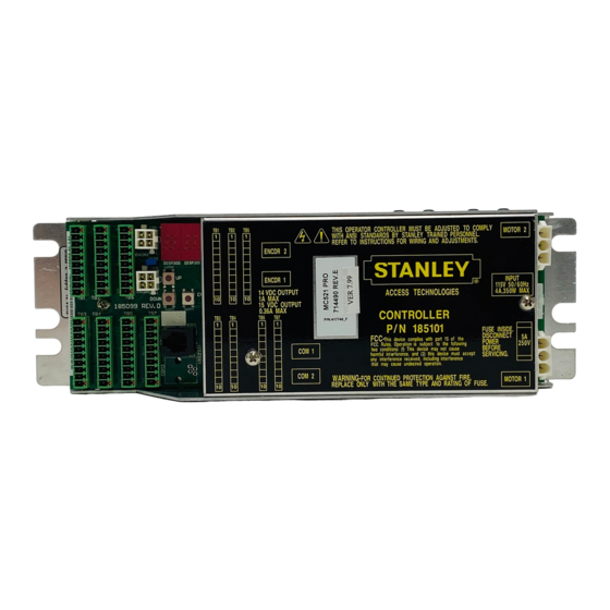
Page 43: Attachment 7: Mc521 Pro Controls And Indicators
MC521 PRO Control Box Attachment 7 MC521 PRO Controls and Indicators (Sheet 1 of 2) SEE DETAIL A JP200 DETAIL A NOTE: See next page for indicators and descriptions 1.800.7.ACCESS • www.stanleyaccess.com • Document # 204090 REV D... - Page 44 MC521 PRO Control Box Attachment 7 MC521 Pro Controls and Indicators (Sheet 2 of 2) ITEM CONTROL/INDICATOR DESCRIPTION Motor 2 Connector P402 Motor No. 2 connector. Power Connector J500 Connection point for incoming line, neutral, and common power wiring. Fuse F500 Controller fuse-- 5 Amp, 250V.
-
Page 45: Attachment 8: Ansi/Bhma And Ul Compliance Requirements
MC521 PRO Control Box Attachment 8 ANSI/BHMA and UL Compliance Requirements for Swinging and Folding Doors (Sheet 1 of 2) Final adjustment and proper operation of the door system must be and shall be performed in the field. Note : These instructions are for informational purposes and do not substitute for review against the current revision of the referenced standards. - Page 46 MC521 PRO Control Box Attachment 8 ANSI/BHMA and UL Compliance Requirements for Swinging and Folding Doors (Sheet 2 of 2) Wiring • To reduce the risk of electric shock proper and reliable grounding is mandatory. See Main Power Wiring Wiring Diagrams instructions and in this guide for grounding techniques.
-
Page 47: Attachment 9: Hand Held Device Troubleshooting Aid
MC521 PRO Control Box Attachment 9 ‘Hand held device’ Troubleshooting Aid—Swing/Bifold (Sheet 1 of 2) Terminal and Pin Description State Dark = door open TB1-8 Bodyguard-T Data Output Light = door closed Function Switch States for TB2 Hold Open Auto ON... - Page 48 (Sheet 2 of 2) Output Control Mode The Output Control allows the user to run the MC521 Pro Control Box in a debug mode. The Output Control is located on the MC521 Troubleshooting Screen. The MC521 Pro firmware needs to be above 7.97 for the Toolbox to have Output Control Mode functionality.
-
Page 49: Attachment 10: Recommended Values
MC521 PRO Control Box Values shown as grayed out do not affect motion of the door and may need to be adjusted to suit the application Attachment 10 Table 1 Recommended Values for Concealed Doors - Motor 1 Index Description... - Page 50 MC521 PRO Control Box Values shown as grayed out do not affect motion of the door and may need to be adjusted to suit the application Attachment 10 Table 2 Recommended Values for Concealed Doors - Motor 2 Index Description...
- Page 51 MC521 PRO Control Box Values shown as grayed out do not affect motion of the door and may need to be adjusted to suit the application Attachment 10 Table 3 Recommended Values for Single Out-Swing Doors Index Description Light Weight Door (100lbs)
- Page 52 MC521 PRO Control Box Values shown as grayed out do not affect motion of the door and may need to be adjusted to suit the application Attachment 10 Table 4 Recommended Values for Single In-Swing Doors Index Description Light Weight Door (100lbs)
- Page 53 MC521 PRO Control Box Values shown as grayed out do not affect motion of the door and may need to be adjusted to suit the application Attachment 10 Table 5 Recommended Values for Dual Egress Swing Doors with Motor 1 as In-Swing...
- Page 54 MC521 PRO Control Box Values shown as grayed out do not affect motion of the door and may need to be adjusted to suit the application Attachment 10 Table 6 Recommended Values for Dual Egress Swing Doors with Motor 2 as In-Swing...
-
Page 55: Attachment 11 Mc521 Pro Controller Fine Tuning
MC521 PRO Control Box Attachment 11 MC521 Pro Controller Fine Tuning (PAGE 1 OF 1) Match your actual door to one from the list of doors described in the attachment. Start by installing these set- tings. Use the guide below to make adjustments to these settings. - Page 56 Stanley Access Technologies, LLC. 65 Scott Swamp Road Farmington, CT 06032 Document # 204090 REV D • www.stanleyaccess.com • 1.800.7.ACCESS...
Need help?
Do you have a question about the MC521 PRO and is the answer not in the manual?
Questions and answers