Advertisement
Quick Links
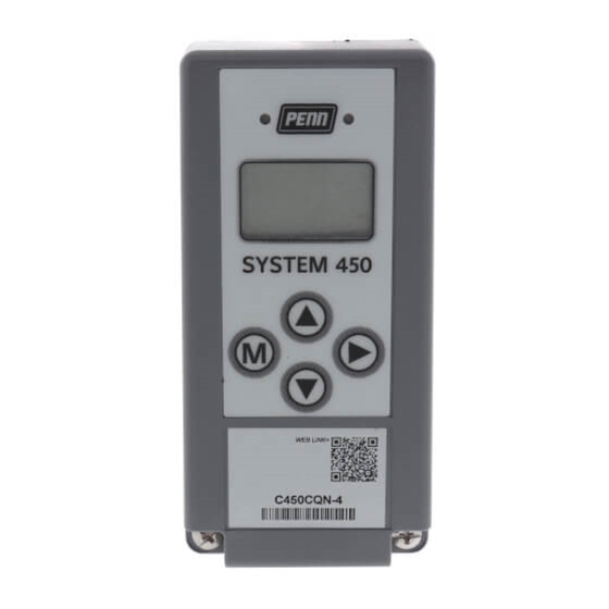
System 450™ Series Control Modules with Relay Outputs
Installation Instructions
C450CBN-1
C450CCN-1
Application
IMPORTANT: Use this System 450 Series Control
Module with Relay Output only as an operating
control. Where failure or malfunction of the System
450 control module could lead to personal injury or
property damage to the controlled equipment or
other property, additional precautions must be
designed into the control system. Incorporate and
maintain other devices, such as supervisory or
alarm systems or safety or limit controls, intended to
warn of or protect against failure or malfunction of
the System 450 control module.
System 450 is a family of modular, digital electronic
controls that is easily assembled and set up to provide
reliable temperature, pressure, and humidity control for
a wide variety of Heating, Air Conditioning, Ventilation,
and Refrigeration (HVACR) and commercial/industrial
process applications.
The System 450 control modules allow you to
configure custom application-specific control systems
with up to three input sensors and ten (relay and/or
analog) outputs, including control systems that can
monitor and control temperature, pressure, and
humidity applications simultaneously.
You can easily install and quickly configure a
stand-alone System 450 control module and sensor in
the field as a replacement control for almost any
temperature, pressure, and humidity control.
C450CxN-1 models are Single-Pole, Double-Throw
(SPDT) relay control modules with Liquid Crystal
Display (LCD) and four-button touch pad User Interface
(UI) that allows you to set up a System 450 control
system. C450CBN-1 models provide one SPDT relay,
C450CCN-1 models provide two SPDT relays.
Refer to the System 450 Series Technical Bulletin
(LIT-12011459) for more detailed information on
designing, installing, setting up, and troubleshooting
System 450 Series control systems. The System 450
technical bulletin can be accessed and downloaded on
the Johnson Controls® Online Product Literature Web
site at the following Web address:
http://cgproducts.johnsoncontrols.com/default.aspx
System 450™ Series Control Modules with Relay Outputs Installation Instructions
Part No. 24-7664-2675, Rev. G
Supersedes December 21, 2009
13
(1/2)
(7/16)
DIN Rail
127
(2-15/16)
Clips
(5)
61
(2-3/8)
1/2 in. Nominal
Trade Size
Conduit Hole
22
(7/8)
Figure 1: System 450 Module Dimensions, mm (in.)
Installation
Location Considerations
Observe the following System 450 location guidelines:
•
Ensure that the mounting surface can support the
module assembly, mounting hardware, and any
(user-supplied) panel or enclosure.
•
Mount the modules upright and plugged together in
a horizontal row where possible (Figure 3). DIN rail
mounting is highly recommended.
•
Mount modules on flat even surfaces.
•
Allow sufficient space for wires and connections.
•
Mount the modules in locations free of corrosive
vapors and observe the ambient operating
conditions in the Technical Specifications.
•
Do not mount the modules on surfaces that are
prone to vibration or in locations where radio
frequency or electromagnetic emissions may
cause interference.
•
Do not install the modules in airtight enclosures.
•
Do not install heat-generating devices in an
enclosure with the modules that may cause the
temperature to exceed the ambient operating limit.
Issued April 27, 2010
11
40
(1-9/16)
4
(3/16)
75
Screw
Slots
(Four)
61
(2-3/8)
1
Advertisement

Related Manuals for Johnson Controls C450CCN-1


Summarization of Contents
Application Overview
Product Description and Capabilities
Details the System 450's modular design, digital electronics, and control capabilities for HVACR and process applications.
Model C450CxN-1 Features
Highlights features of C450CxN-1 models, including LCD display, touch pad UI, and SPDT relay configurations.
Important Usage and Safety Notes
Emphasizes critical precautions for using the System 450 control module to prevent injury or property damage.
Further Technical Documentation
Directs users to the System 450 Series Technical Bulletin for detailed design, installation, and troubleshooting information.
Installation and Mounting
Location Considerations
Provides guidelines for selecting appropriate installation locations, considering mounting surfaces, space, and environmental factors.
Module Mounting Methods
Details procedures for mounting System 450 modules using 35 mm DIN rail or directly to wall surfaces.
Wiring and Connections
Electrical Safety Precautions
Highlights critical warnings regarding electrical shock hazards and the necessity of isolating all power supplies before wiring.
Wiring Best Practices
Outlines important wiring practices, including using copper conductors, adhering to ratings, and separating low-voltage from high-voltage wiring.
Wiring Terminal Identification
Refers to Figure 2 for identifying C450CxN-1 wiring terminals for supply power, sensor inputs, and relay outputs.
System Setup and Configuration
System 450 Component Requirements
Lists the essential components for a System 450 control system, including control modules, sensors, and outputs.
Module Assembly and Power-Up
Guides users through assembling control and expansion modules and applying supply power to the module assembly.
User Interface Setup Procedures
Explains how to use the back-lit LCD and four-button touch pad UI to set up the System 450 control system.
Accessing Setup Screens
Details the procedure for accessing the System 450 setup screens from the Main screen via button presses.
Sensor Setup and Configuration
Covers setting up input sensors, including selecting sensor types and configuring temperature offsets for accurate readings.
Relay Output Setup
Provides step-by-step instructions for configuring relay outputs, including sensor selection, ON/OFF values, and minimum times.
Analog Output Setup
Details the configuration process for analog outputs, covering setpoint, endpoint, signal strength, and integration constants.
Technical Specifications and Compliance
Product and Performance Specifications
Lists detailed technical specifications for the C450CxN-1 module, including power, operating conditions, input signals, and output ratings.
Emissions Compliance Information
Presents compliance statements for United States (FCC) and Canadian emissions regulations relevant to the digital apparatus.
Need help?
Do you have a question about the C450CCN-1 and is the answer not in the manual?
Questions and answers