Table of Contents
Advertisement
Quick Links
Download this manual
See also:
User Manual
Advertisement
Table of Contents

Related Manuals for ABB M2231 Series


Summary of Contents for ABB M2231 Series
- Page 1 │ 2TMD041600D0107 09.04.2018 Product manual ABB-Welcome M2231.-. 4.3" video hands-free indoor station...
-
Page 2: Table Of Contents
Table of contents Notes on the instruction manual ........................4 Safety ................................4 Intended use ..............................4 Environment ..............................5 ABB devices ............................5 Product description ............................6 Control elements ..........................6 Technical data ............................... 8 Mounting/Installation ............................9 Requirement for the electrician ......................9 General installation instructions ....................... - Page 3 Table of contents Operation ..............................36 Incoming a call ..........................36 Display and volume settings ......................37 Communication menu ........................38 9.3.1 Overview ............................38 9.3.2 Intercom call ...........................38 9.3.3 Call guard unit ..........................39 9.3.4 Broadcast ............................39 9.3.5 Switch actuator ..........................40 Cleaning ............................
-
Page 4: Notes On The Instruction Manual
Please keep this manual in a safe place. If you pass the device on, also pass on this manual along with it. ABB accepts no liability for any failure to observe the instructions in this manual. Safety... -
Page 5: Environment
ABB devices All packaging materials and devices from ABB bear the markings and test seals for proper disposal. Always dispose of the packing materials and electric devices and their components via an authorized collection facility or disposal company. -
Page 6: Product Description
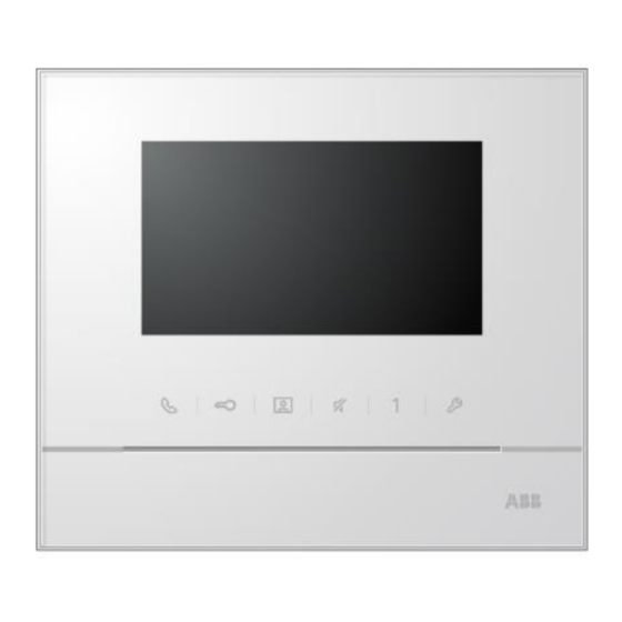
Product description Product description Control elements Fig. 1: Control elements Function 4.3" Color display Communication button ■ While a call is coming, press this button to activate the communication within 30 s and press again to end the call. ■ In standby mode, press this button to enter the communication menu. - Page 7 Product description Mute button ■ In standby mode, press this button to mute ringtone of this indoor station. ■ In standby mode, long press this button to mute ringtone of all indoor stations in the same apartment. ■ While a call is coming, press this button to reject the call. ■...
-
Page 8: Technical Data
Technical data Technical data Designation Value Display resolution 480 x 272 Display size 4.3” Operating temperature -10 °C…+55 °C Storage temperature -40 °C…+70 °C Protection IP 30 Single-wire clamps 2 x 0.28 mm² - 2 x 0.75 mm² Fine-wire clamps 2 x 0.28 mm²... -
Page 9: Mounting/Installation
Mounting/Installation Mounting/Installation Warning Electric voltage! Dangerous currents flow through the body when coming into direct or indirect contact with live components. This can result in electric shock, burns or even death. – Disconnect the mains power supply prior to installation and/or disassembly! –... -
Page 10: General Installation Instructions
Mounting/Installation General installation instructions ■ Terminate all branches of the wiring system via a connected bus device (e.g., indoor station, outdoor station, system device). ■ Do not install the system controller directly next to the bell transformer and other power supplies (to avoid interference). -
Page 11: Mounting
Mounting/Installation Mounting 7.3.1 Recommended installation height Fig. 3: Recommended installation height 7.3.2 Dismantling Fig. 4: Dismantiling Open the housing of the panel by pulling the clamp at the bottom of the device. │11 Product manual 2TMD041600D0107... -
Page 12: Installation Dimension
Mounting/Installation 7.3.3 Installation dimension Fig. 5: Installation dimension ■ The bottom of the device has screw holes for fastening on the wall according to the above dimension instructions. ■ In addition, the bottom of the device can be fixed to the existing flush-mounted box. The dimension of the compatible flush-mounted box is shown in illustration above. -
Page 13: Surface-Mounted Installation
Mounting/Installation 7.3.6 Surface-mounted installation Mounted on the wall Fig. 7: Mounted on the wall Affix the bottom of the device to the wall. ■ ■ Latch the upper part of the device onto the bottom. Place the upper side of the device on the lock-in lugs and then press the bottom side onto the bottom part of the device until it is caught by the clamp. -
Page 14: Desktop-Mounted Installation
Mounting/Installation 7.3.7 Desktop-mounted installation Fig. 9: Desktop-mounted installation Affix the bottom of the device to the desktop bracket. Latch the upper part of the device onto the bottom part. Place the upper side of the device on the lock-in lugs and then press the bottom side onto the bottom part of the device until it is caught by the clamp. - Page 15 Mounting/Installation Mounted with back cover Fig. 11: Mounted with back cover ■ Affix the back cover inside the wall directly. ■ Latch the upper part of the device onto the bottom part. Place the upper side of the device on the lock-in lugs and then press the bottom side onto the bottom part of the device until it is caught by the clamp.
-
Page 16: Cavity Wall Installation
Mounting/Installation 7.3.9 Cavity wall installation Fig. 13: Cavity wall installation [1] Attach a pair of supporting brackets to the back cover of the indoor station. Place 4 screws through the back cover and attach with 4 claw brackets. [2] Rotate 4 claw brackets to attach to the supporting brackets and pull the rubber bands around the corner of the claw brackets to fix the claws. -
Page 17: Commissioning
Commissioning Commissioning Device settings Fig. 15: Device settings Description Station Select switch to set the address of default outdoor station. X10 X1 Selector switches to set the address (tens and units digits) of the indoor station. X200 X100 Dip switches to set the address (hundreds digits) of the indoor station. Master/slave function Only one indoor station in each apartment must be set as "Master"... - Page 18 Commissioning Connection Fig. 16: Connection Description Connection for the doorbell pushbutton ■ Connection for the system controller ■ When using several indoor stations: connection for the internal bus │18 Product manual 2TMD041600D0107...
-
Page 19: Intercom Call Settings
Commissioning Intercom call settings Fig. 17: Intercom call settings Functions Choose the previous selection or scroll up Choose the next selection or scroll down Confirm the selection you choose or enter to edit it Return to the previous screen Add a new intercom list. A total of 32 intercom lists can be added Existing intercom list: Press button √... - Page 20 Commissioning Add an intercom call Fig. 18: Add an intercom call Functions Enter to choose the call type: – an external intercom means a call from different apartments – an internal intercom means a call within the same apartment Enter to change the target address, from 001 to 250. *If the call type is the internal intercom, there is no need to set the target address.
-
Page 21: Switch Actuator Settings
Commissioning Switch actuator settings Fig. 19: Switch actutor settings Functions Existing switch actuator list. Press button √ to modify the settings. Add a new actuator list. A total of 10 switch actuator lists can be added. Enter to change target address with “+” or “-” button from 001 to 199. Rename the switch actuator list: Scroll through letters of the alphabet or numbers one by one with “+”... -
Page 22: Program Button Settings
Commissioning Program button settings Fig. 20: Program button settings Functions Set functions for the program button, e.g. releasing second lock, calling guard unit, intercom call, enabling the switch actuator. *Second lock means the lock is connected with an outdoor station (NC-NO-COM) *Only the existing intercom call list and switch actuator list can be assigned to the program button. -
Page 23: Call Forward Settings
Commissioning Call forward settings Fig. 21: Call forward settings Functions Enable/disable the call forward function. Enter to choose a call type, including indoor or guard unit. Enter to change the target address if the call type is an indoor station. *If the call forward function is activated, the auto unlock function will be disabled. -
Page 24: Auto Unlock Settings
Commissioning Auto unlock settings Fig. 22: Auto unlock settings Functions Enable/disable the auto unlock function. Enable/disable the auto unlock during Time 1. Set starting time and ending time for Time 1. Enable/disable auto unlock during Time 2. Set starting time and ending time for Time 2. *If you activate the auto unlock function without setting exact working time, this function will be available for 10 hours. -
Page 25: Outdoor Station Password Settings
Commissioning Outdoor station password settings Fig. 23: Outdoor station password settings Functions Enable/disable the password functions. Enter a 3-8 digit password. *only available with the keypad. *The function can only be set in the master indoor station. │25 Product manual 2TMD041600D0107... -
Page 26: Ringtone Settings
Commissioning Ringtone settings Fig. 24: Ringtone settings Functions Select the bell sound for the default outdoor station. Select the bell sound for other outdoor stations. Select the bell sound for the apartment door. Select the bell sound for others, e.g., a call from the guard unit, or an intercom call from other apartments. -
Page 27: Volume Settings
Commissioning Volume settings Fig. 25: Volume settings Functions Set the volume of bell sound. Enable/disable the feedback tone that sounds when the touch button is pressed. The ringtone can be set as fixed or cycled. │27 Product manual 2TMD041600D0107... -
Page 28: Date And Time Settings
Commissioning 8.10 Date and time settings Fig. 26: Date and time settings Functions Set the date. Set the time. Enable/disable the summertime function. │28 Product manual 2TMD041600D0107... -
Page 29: Other Settings
Commissioning 8.11 Other settings Fig. 27: Other settings Functions Enable/disable the auto full screen function. Enable/disable the door status check function (only available if sensor is installed with outdoor station); flashes when the door is open). Enable/disable the auto-snapshot function. *The function is available in M22302-. -
Page 30: Blacklist Settings
Commissioning 8.12 Blacklist settings Fig. 28: Blacklist settings Functions Existing blacklist: Press button √ to modify the settings. Add new blacklist(s). A total of 32 blacklists can be added. Enter to change the target address with “+” or “-” button from 001 to 250. *The function only can be set in the master indoor station. -
Page 31: History Review
Commissioning 8.13 History review Fig. 29: History review Functions Up to 100 events can be recorded in the history menu. – If the snapshot function is enabled, an icon will display. If snapshot function is not enabled, icon will not display. –... -
Page 32: Camera List
Commissioning 8.14 Camera list Fig. 30: Camera list │32 Product manual 2TMD041600D0107... - Page 33 Commissioning Functions Display status of the camera list. Only if the list is enable, user can make an surveillance according to this list, and also user can edit each surveillance object in the list. Display the camera from camera interface. Press this button to enable or disable camera list.
-
Page 34: Language Settings
Commissioning 8.15 Language settings Fig. 31: Language settings 8.16 Information Fig. 32: Information Scan QR code to get detailed instructions. │34 Product manual 2TMD041600D0107... -
Page 35: Reset Factory Default
Commissioning 8.17 Reset factory default Fig. 33: Reset factory default Functions Reset all settings: Reset the device and restore all default configurations. The operation does not delete the programmed data and history such as intercom lists and switch actuator lists. Clear all data: Delete all programmed data and history. -
Page 36: Operation
Operation Operation Incoming a call Fig. 34: Incoming a call During a call, the following functions are available: Functions Press this button to accept the incoming call. During a call, press this button to end the call. Press this button to open the door from where call originated. ■... -
Page 37: Display And Volume Settings
Operation Display and volume settings Fig. 35: Display and volume settings Hold button for 3s to enter the display and volume settings menu during a call. The following functions are available: Functions Navigation buttons (up, down, confirm, cancel, etc.) Press the navigation buttons as needed. Speech volume (can only be adjusted during conversation) Saturation Brightness... -
Page 38: Communication Menu
Operation Communication menu 9.3.1 Overview Press button to enter the communication menu. The following functions are available: Functions Intercom call Click on the existing call list to make an intercom call. Call to guard unit Call guard unit directly. Broadcast Enable the broadcast function in this menu. -
Page 39: Call Guard Unit
Operation 9.3.3 Call guard unit Fig. 37: Call guard unit 9.3.4 Broadcast Fig. 38: Broadcast │39 Product manual 2TMD041600D0107... -
Page 40: Switch Actuator
Operation 9.3.5 Switch actuator Fig. 39: Switch actuator Set the actuator list in the “system settings-switch actuator” menu first. After choosing a list, press button √ to enable the lock or light that is connected to the switch actuator. │40 Product manual 2TMD041600D0107... -
Page 41: Cleaning
Operation Cleaning Caution Risk of damage to the screen surface The screen surface can be damaged by hard or sharp objects! Never use such objects for entries on the touch screen monitor. – Use your finger or a plastic stylus. The screen surface can be damaged by cleaning fluids or abrasive agents! –... - Page 42 We reserve the right to at all times make technical changes as well as changes to the contents of this document without prior notice. The detailed specifications agreed to at the time of ordering apply to all orders. ABB accepts no responsibility for possible errors or incompleteness in this document.
- Page 43 Km 9 National Highway 1A , The detailed specifications agreed P.O.Box 11070 Dubai-UAE Hoang Liet, Hoang Mai, Hanoi, upon apply for orders. ABB accepts T : +971 4 3147 586 Vietnam no responsibility for possible errors F : +971 4 3401 541 T : +84 4 3861 1010 or incompleteness in this document.
- Page 44 Error! Use the Home tab to apply Überschrift 1 to the text that you want to appear here. Copyright 2018 ABB © All rights reserved │44 Product manual 2TMD041600D0107...
Need help?
Do you have a question about the M2231 Series and is the answer not in the manual?
Questions and answers