Table of Contents
Advertisement
Quick Links
Download this manual
See also:
Operating Manual
Advertisement
Table of Contents

Subscribe to Our Youtube Channel
Summary of Contents for REMKO SQW 400
-
Page 1: Electrical Wiring
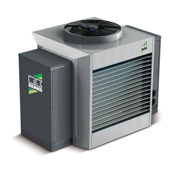
Electrical wiring REMKO modular energy control centre SQW 400 Instructions for Technician Read the instructions prior to performing any task! 0144-2018-07 Edition 2, en_GB... - Page 2 Read these operating instructions carefully before commis- sioning / using this device! These instructions are an integral part of the system and must always be kept near or on the device. Subject to modifications; No liability accepted for errors or mis- prints! Translation of the original...
-
Page 3: Table Of Contents
Table of contents Safety and usage instructions......................4 1.1 General safety notes........................4 1.2 Identification of notes........................4 1.3 Personnel qualifications........................4 1.4 Dangers of failure to observe the safety notes................4 1.5 Safety-conscious working....................... 4 1.6 Safety notes for the operator......................5 1.7 Safety notes for installation, maintenance and inspection.............. -
Page 4: Safety And Usage Instructions
REMKO modular energy control centre Safety and usage instructions CAUTION! This combination of symbol and signal word 1.1 General safety notes warns of a potentially hazardous situation, which if not avoided may cause injury or mate- Carefully read the operating manual before com- rial and environmental damage. -
Page 5: Safety Notes For The Operator
"certificate of warranty" to with all applicable regional regulations. REMKO GmbH & Co. KG at the time when the Local regulations and laws such as Water units are purchased and commissioned. -
Page 6: Transport And Packaging
REMKO modular energy control centre 1.11 Transport and packaging The devices are supplied in a sturdy shipping con- tainer. Please check the equipment immediately upon delivery and note any damage or missing parts on the delivery and inform the shipper and your contractual partner. -
Page 7: Electrical Wiring
Electrical wiring 2.1 System layout The heat pump SQW 400 can be used both as a single unit (monoblock) and also as a cascade. Single system layout SQW 400 Fig. 1: System layout for single unit Cascade system layout SQW 400... -
Page 8: Electrical Wiring General Notes
REMKO modular energy control centre 2.2 Electrical wiring general notes WARNING! A power supply cable must be laid to both to the outdoor unit and, separately, to the Smart All cable sizes are to be selected according to Control. VDE 0100. Special attention should be given to... -
Page 9: Electrical Wiring
2.3 Electrical wiring When connecting the control line, make sure that polarity is correct. To connect up the electrics, remove the right If the outdoor unit is installed on a roof, it and cladding panel after unfastening the screws. the supporting structure must be earthed sepa- rately (connection to lightning conductors or foundation earth/ground feature). - Page 10 REMKO modular energy control centre Cable inlets 2278 DG21 PG16 PG21 PG29 Fig. 5: Cable inlets A: Side view 2: Mains cable inlet electrical auxiliary heater 3: Mains cable inlet from underneath Ø DG53 B: View from below C: Compressor side 4: Mains cable inlet electrical auxiliary heater from underneath Ø...
-
Page 11: Overview Of Electrical Cables
2.4 Overview of electrical cables Fig. 6: Heat pump without Smart Control... - Page 12 REMKO modular energy control centre Fig. 7: Heat pump with Smart Control...
-
Page 13: Electrical Wiring Diagram
2.5 Electrical wiring diagram Signal circuit wiring diagram Eev1 Eev2 0-10V Pump 0-10V Legend: Fan motor Heat dissipation sensor Flow probe Outside temperature High pressure switch Drinking water sensor Pump: Primary pump Infeed water temperature (RL) ThC: Overtemperature alarm for fan Steam temperature from EVI circuit ThP: Overtemperature alarm for pump... - Page 14 REMKO modular energy control centre Power circuit wiring diagram Legend: Pmr: Phase monitoring relay Compressor trace heating Pump: Primary pump Comp: Compressor Compressor contact 3-way valve Compressor motor protection Control command e-heating element 9 kW Main power supply isolator switch...
- Page 15 Electrical connection diagrams control board via building control technology Legend: ID9: Emergency stop potential-free Hot water probe NO8: Compressor status potential-free ID5: Inlet hot water operation potential-free NO9: Defrost status potential-free ID6: Inlet Smart-Serv operation potential-free N10: Output general alarm signal potential-free ID7: Switching heating/cooling potential-free N12:...
- Page 16 REMKO modular energy control centre Electrical connection diagrams heating recovery (Smart-Heat) Legend: Main supply disconnector Gas temperature before 4WV Trasformer Recovery water inlet temperature TrP: Trasformer Recovery water outlet temperature Farben: DHP: DHW pump for recovery function black 3 way valve...
-
Page 17: Index
Index Cable inlets ......10 Safety Dangers of failure to observe the safety notes . - Page 18 REMKO modular energy control centre...
- Page 20 SFlb Customer Service Our equipment operates precisely and reliably. However, in the event of a fault, REMKO customer service is quickly at the scene. Our comprehensive network of experienced dealers always guarantees quick and REMKO GmbH & Co. KG reliable service.


Need help?
Do you have a question about the SQW 400 and is the answer not in the manual?
Questions and answers