Table of Contents
Advertisement
Installation and Operating Instructions
Thermal Energy Meter (Compact Heat Meter, Combined Heat/Cooling Energy Meter)
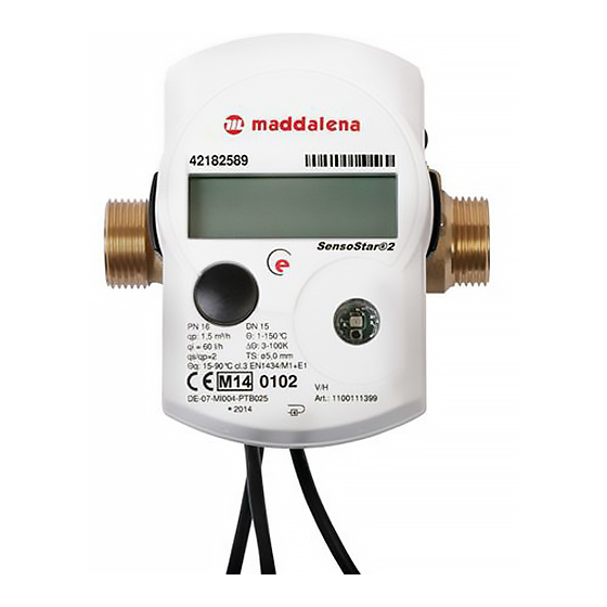
microCLIMA/SENSOSTAR®2/2+ MSH
Model MSH DE-07-MI004-PTB001 (MID heat)
Model QStar DE-08-MI004-PTB005 (MID heat)
1
Application and Function
Thermal energy meter designed for the measurement of the consumed thermal energy in a closed heating system
or heating / cooling system.
2
Contents of the Package
-
Thermal energy meter consisting of a calculator, a flow sensor and two temperature sensors, connected
permanently
-
Installation kit MSH-SStar, -VStar, -MStar, -AStar or QStar (depending on type)
-
Depending on type of the flow sensor (label):
EAS identification "EN14154" (IST)
EAS identification "EN14154"(TE1)
EAS identification "EN14154" (M60)
EAS identification "EN14154"(A1)
-
Installation and Operating Instructions
3
General Information
-
Valid standards for the application of heat meters: EN 1434, parts 1 – 6; the Measuring Instruments
Directive 2004/22/EC, Annexes I and MI-004, and the relevant national verification regulations.
-
For the selection, installation, commissioning, monitoring and maintenance of the instrument observe the
standard EN 1434 part 6 as well as Annex 22 of the verification regulations (for Germany).
-
National regulations for the consumption measurement of cooling must be observed.
-
The technical regulations for electrical installations must be observed.
-
This product fulfils the requirements of the European Council Directive on Electromagnetic Compatibility
(EMC Directive) 2004/108/EC.
-
The identification plate of the instrument and the seals must not be removed or damaged – otherwise the
guarantee and the approved application of the instrument are no longer valid!
-
To achieve measurement stability of the meter it is necessary that the water quality meets the
requirements of the AGFW-recommendation FW-510 and the document VDI (Association of German
Engineers) VDI 2035.
-
The heat meter left the factory in conformance with all applicable safety regulations. All maintenance and
repair work is to be carried out only by qualified and authorized technical personnel.
-
The instrument must be stored and transported at temperatures above-freezing.
-
Instruments with activated radio function are not allowed on air freight.
-
The correct installation point in the system must be chosen: forward or return flow, as stated on the type
identification label.
-
The temperature sensor cables and the cable between the calculator and flow sensor must not be kinked,
rolled up, lengthened or shortened.
-
To clean the heat meter (only if necessary) use a slightly moist cloth.
-
To protect against damage and dirt the heat meter should only be removed from the packaging directly
before installation.
-
If more than one heat meter is installed in one unit, care must be taken to ensure that all the meters have
the same installation conditions.
-
All specifications and instructions listed on the data sheet and in the Application Notes must be adhered
to.
Doc. code 1080100090
Version: 2015_03_03
1
Advertisement
Table of Contents

Related Manuals for MADDALENA microCLIMA/SENSOSTAR 2+ MSH


Summary of Contents for MADDALENA microCLIMA/SENSOSTAR 2+ MSH
- Page 1 Installation and Operating Instructions Thermal Energy Meter (Compact Heat Meter, Combined Heat/Cooling Energy Meter) microCLIMA/SENSOSTAR®2/2+ MSH Model MSH DE-07-MI004-PTB001 (MID heat) Model QStar DE-08-MI004-PTB005 (MID heat) Application and Function Thermal energy meter designed for the measurement of the consumed thermal energy in a closed heating system or heating / cooling system.
- Page 2 Further information can be obtained at www.engelmann.de. Instruments which have been replaced or exchanged must be disposed of according to relevant environmental regulations. The display is deactivated and can be activated for one minute by pushing the button (except calculator without additional interfaces).
- Page 3 Screw in the heat meter tightly by hand and then tighten additionally with a suitable wrench to the mechanical end stop (metal-to-metal). Detach the calculator and mount it, or rotate it to the best position for read-out. ® Installation of S type MSH-MStar in a single pipe connection piece (thread M60x1,5) ENSO The multi-jet flow sensor type MSH-VStar has an external thread M60x1,5 connection as described in EN 14154...
- Page 4 Also, please pay attention that the blind hole in the plastic adapter is properly lined up with the metal pin in the inside bottom of the EAT on the flow outlet (in rare cases, this pin may not be present: in this case, it is not necessary for installation.) Plastic adapter: blind hole Directional arrows...
- Page 5 Mounting the temperature sensors 6 mm of the MSH-AStar 5.2.1 Direct-mounting the temperature sensors of the MSH-AStar Important notes Close the shut-off valves and make sure that no hot water can escape upon removal of the blind plug or the old temperature sensor! Prepare both temperature sensors: Push the O-ring into the middle groove.
- Page 6 Display The calculator has a liquid crystal display with 8 digits and special characters. The values that can be shown are divided into three display loops. All data is retrieved using the push button next to the display. At the start you are automatically in the main loop (1st level). By pressing the push-button longer than 4 seconds you change to the next display loop.
- Page 7 9) Serial number 10) Firmware version Level 3 / Statistics loop 1) Previous reading date alternating with its value. 2.-16) Monthly values: dates alternating with their Alternatively, the total volume or tariff values can be values. Alternatively, the total volume or tariff values can displayed be displayed Up to the end of the month the consumption and reading date for that month will be shown as 0.
- Page 8 Power supply 3 V lithium battery Standard: 10 years; 6 years + 1 with pulse output: see Battery lifetime, estimated years “Influencing_factors_battery_lifetime”. Data storage PROM; daily Display 8 digits + special characters standard Infrared Interfaces M-Bus galvanically isolated; M-Bus galvanically isolated + 2 pulse inputs; optional wireless M-Bus;...
- Page 9 EN 13757-1_2002, -2_2004, -3_2004 Communication systems for meters and remote reading of meters The M-Bus A Documentation, Version 4.8, M-Bus User group TI Technical Journal Texas Instruments Technical Journal Vol. 8, 1991 M-Bus 9.3.2 Additional technical specifications The installation has to fulfil the requirements of the relevant norms, standards and literature (see paragraph 9.3.1) and the specifications as follows: Maximum voltage M-Bus 42 V...
- Page 10 9.4.1 Technical data radio Frequency 868 MHz Transmission power up to 12 dBm Protocol wireless M-Bus based on EN 13757-3 Selectable modes S1 / T1 / C1 Telegrams short telegram in conformity to AMR (OMS-Spec_Vol2_Primary_v301): energy (heat/cooling energy, pulse input 1, pulse input 2), total volume, flow, power, hint flag, return flow temperature, temperature difference long telegram for walk-by read-out: energy (heat/cooling energy, pulse input 1, pulse input 2), total volume, hint flag, 15 monthly values...
- Page 11 General information about pulse inputs It is important to note that the acknowledged state of the art technology rules and the relevant legal restraints (international and local; see par. 9.5.1 “Relevant norms, standards and literature on the pulse inputs”) are to be observed.
- Page 12 1000 litres / kWh / pulse without unit Installation notes for the pulse inputs It is important that the pulse cables not be affected by (or exposed to) the M-Bus voltage! Check the polarity of pulse generators with ‘open collector’ outputs. The cable wires must not touch each other during installation, otherwise pulses will be counted in the instrument.
- Page 13 Binary display Description Hexadecimal display 1 at first place Check sum error E 40 1 at second place PROM defective E 20 1 at third place Instrument has been reset E 10 1 at fourth place Scanning coil defective E 08 1 at fifth place Reference sensor defective E 04...
- Page 14 69168 Wiesloch-Baiertal – Germany Tel: +49 (0)6222-9800-0 Fax:+49 (0)6222-9800-50 E-Mail: info@engelmann.de www.engelmann.de 14 Contacts Maddalena S.p.A. Via G.B. Maddalena, 2/4 33040 Povoletto (UD) – Italy Tel.: +39.0432.634811 Fax.: +39.0432.679820 www.maddalena.it Subject to technical change without prior notice. Doc. code 1080100090...
Need help?
Do you have a question about the microCLIMA/SENSOSTAR 2+ MSH and is the answer not in the manual?
Questions and answers