Advertisement
Quick Links
Installation and Operating Instructions
Calculator with Ultrasonic Flow Sensor (Heat Meter, Cooling Energy Meter, Combined
Heat/Cooling Energy Meter)
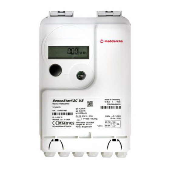
microCLIMA ULTRA/SENSOSTAR®2C_US
Certificate no:
DE-09-MI004-PTB018 (MID heat); 22.72/09.01 (National German cooling)
1
Application and Function
Thermal energy meter (heat meter, cooling energy meter or combined heat/cooling meter) designed for the
measurement of the consumed thermal energy in a closed heating or cooling or heating/cooling system.
2
Scope of delivery
-
Calculator with ultrasonic flow sensor (heat meter, cooling energy meter, combined heat/cooling energy
meter)
-
Installation kit: 5 self-lock seals + 5 seal-wires; O-ring ; 2 screws + 2 dowels for direct screw mounting
-
2 gaskets for the flow sensor
-
Installation and Operating Instructions
3
General Information
-
Valid standards for the application of heat meters: EN 1434, parts 1 – 6; the Measuring Instrument
Directive 2004/22/EC, Annexes I and MI-004; and the relevant national verification regulations.
-
For the selection, installation, commissioning, monitoring and maintenance of the instrument observe the
standard EN 1434 part 6 as well as Annex 22 of the verification regulations (for Germany).
-
National regulations for the consumption measurement of cooling must be observed.
-
The technical regulations for electrical installations are to be observed.
-
This product fulfils the requirements of the European Council Directive on Electromagnetic Compatibility
(EMC Directive) 2004/108/EC.
-
The identification plate of the instrument and the seals must not be removed or damaged – otherwise the
guarantee and the approved application of the instrument are no longer valid!
-
To achieve measurement stability of the meter is it necessary that the water quality meet the requirements
of the AGFW-recommendation FW-510 and the document VDI (Association of German Engineers) VDI 2035.
-
The heat meter left the factory in conformance with all applicable safety regulations. All maintenance and
repair work is to be carried out only by qualified and authorized technical personnel.
-
The instrument must be stored and transported at temperatures above-freezing.
-
Instruments with activated radio function are not allowed on air freight.
-
The correct installation point in the system must be chosen: forward or return flow, as stated on the type
identification label.
-
The temperature sensor cables and the cable between the calculator and flow sensor must not be kinked,
rolled up, lengthened or shortened.
-
To clean the heat meter (only if necessary) use a slightly moist cloth.
-
To protect against damage and dirt the meter should only be removed from the packaging directly before
installation.
-
If more than one meter is installed in one unit, care must be taken to ensure that all the meters have the
same installation conditions.
2015_03_03
1
Advertisement

Related Manuals for MADDALENA microCLIMA ULTRA


Summary of Contents for MADDALENA microCLIMA ULTRA
- Page 1 Installation and Operating Instructions Calculator with Ultrasonic Flow Sensor (Heat Meter, Cooling Energy Meter, Combined Heat/Cooling Energy Meter) microCLIMA ULTRA/SENSOSTAR®2C_US Certificate no: DE-09-MI004-PTB018 (MID heat); 22.72/09.01 (National German cooling) Application and Function Thermal energy meter (heat meter, cooling energy meter or combined heat/cooling meter) designed for the measurement of the consumed thermal energy in a closed heating or cooling or heating/cooling system.
- Page 2 All specifications and instructions listed on the data sheet and in the Application Notes must be adhered to. Further information can be obtained at www.engelmann.de. Instruments which have been replaced or exchanged must be disposed of according to relevant environmental regulations. The display is deactivated and can be activated for one minute by pushing the button (except calculator without additional interfaces).
- Page 3 Mounting position See section 5 Installation for Cooling Applications Cooling meter Straight pipe sections None required Accuracy class 1:100 or 1:50 Maximum overload 2.8 x q Nominal pressure PN 16, PN 25 IP54 For heat meter Protection class flow sensor IP65 For cooling meter (optional for heat meter) Max.
- Page 4 DN40 15.4 DN50 14.3 DN65 24.4 DN80 31.6 DN100 56.0 Dimensions Threaded connection Flange connection Øc Ød Øe PN bar holes m³/h [mm] [mm] m³/h G 1¼ B G 1¼ B G 1¼ B G 2 B Integration in the Heating System Please inspect and check all dimensions to be sure that there is sufficient space in the intended location for installation of the flow sensor.
- Page 5 If the flow sensor is being installed in the common return flow of two heat systems, e.g. heating and hot water, the mounting location must be sufficiently separated from the T-piece, that is, at least 10 x DN from the T-piece, so that the different water temperatures are well-mixed before reaching the sensor.
- Page 6 All technical data specified in the flow sensor data sheet and instructions must be adhered to. The instrument identification and the seals required for verification of the flow sensor must not be damaged or removed – otherwise the guarantee and verification of the instrument no longer apply! Transport of the flow sensor is only permissible in the original packaging.
- Page 7 Connection 2-wire-system Connection 4-wire-system Cables that are too long should not be rolled up tightly into an ‘air-core coil’. The cables should either be laid out disordered, or rolled up loosely into a wide coil which can be turned and tied into an ‘8’. At delivery, the display shows ‘ERR 03’...
- Page 8 Level 1/Main loop 2) Segment test, all 4) Total flow volume in m³ segments triggered simultaneously 1) Standard display: total 3) Heat energy at last heat energy; alternating reading date alternating display: cooling energy with last reading date (for heating/cooling meter) 5) Current power in kW 7) Current date...
- Page 9 9) Return flow or forward flow temperature sensor type and mounting 11), 13), 15) Maximum 12), 14), 16) Maximum position power value alternating flow value alternating with with date and time of date and time of occurrence occurrence Level 3/Statistics Loop 1) Previous reading date alternating with its value.
- Page 10 13 Additional Interfaces and Power Supply 13.1 Connection of additional interfaces and power supply The following are options that the calculator can be equipped with at the factory (state when ordering) and will vary depending on the individual calculator. - Feed the cable to be connected (cable diameter 3.5 to 6.5 mm) through an opening on the bottom edge of the calculator housing into the space containing the terminal strips.
- Page 11 13.2.1 General information about the M-Bus interface It is important to note that the acknowledged state of the art technology rules and the relevant legal restraints (international and local; see 13.2.2 “Relevant norms, standards and literature on the M-Bus”) are to be observed. The installation has to be performed by authorized, skilled persons.
- Page 12 If fewer read-outs are carried out, the unused ‚credit’ is stored in the instrument and can be used later. During M-Bus communication with the calculator the other interfaces (push-button, optical interface) of the device cannot be used. 13.2.6 M-Bus addresses Calculators with the M-Bus option can be addressed primarily or secondarily.
- Page 13 random key per instrument Type of telegram Short telegram in conformity to AMR (OMS- Spec_Vol2_Primary_v301) Short telegram (AMR) Long telegram for walk-by read-out *Factory settings may vary from the above. 13.3.3 Activation of the radio interface The radio interface leaves the factory deactivated. It can be activated as follows: a) Without using additional software the radio function can be activated by pressing the push-button for over 3 seconds while the display is showing the item ‘M-Bus address’, (see section 10 “Display”...
- Page 14 13.4.2 Technical data pulse inputs Pulse input class CMOS; IB according to EN 1434-2:2007 Internal pull-up voltage + 3 V DC Internal pull-up resistance 2 MΩ Current = 1.5 µA High-level threshold U ≥ 2 V Low-level threshold U ≤ 0.5 V 13.4.3 Electrical requirements on the pulse output of the instrument to be connected (e.g.
- Page 15 Example 3: Display 1234567,8 GJ => pulse value for energy pulse output = 0,1 GJ/pulse 13.5.2 Pulse output for volume (OUT2-Volume) One pulse is generated by the pulse output for volume when the second-to-last digit of the volume display is increased by one.
- Page 16 Example: Temperature sensor switched Message Alternating hexadecimal message displayed (LCD) Display location Alternating binary message displayed (LCD) When a message sign appears in the standard display (total heat, total cooling or alternating total heat and cooling energy), with the exception of the messages ’reset’ (10), (01), (02), (03), (08) and (18), the instrument must be exchanged and sent to the supplier for examination.
- Page 17 Engelmann Sensor GmbH Rudolf-Diesel-Str. 24-28 69168 Wiesloch-Baiertal Germany Tel: +49 (0)6222-9800-0 Fax: +49 (0)6222-9800-50 E-Mail: info@engelmann.de www.engelmann.de 17 Contact Maddalena S.p.A. Via G.B. Maddalena, 2/4 33040 Povoletto (UD) – Italy Tel.: +39.0432.634811 Fax.: +39.0432.679820 www.maddalena.it Subject to technical change. 2015_03_03...
Need help?
Do you have a question about the microCLIMA ULTRA and is the answer not in the manual?
Questions and answers