Advertisement
Quick Links
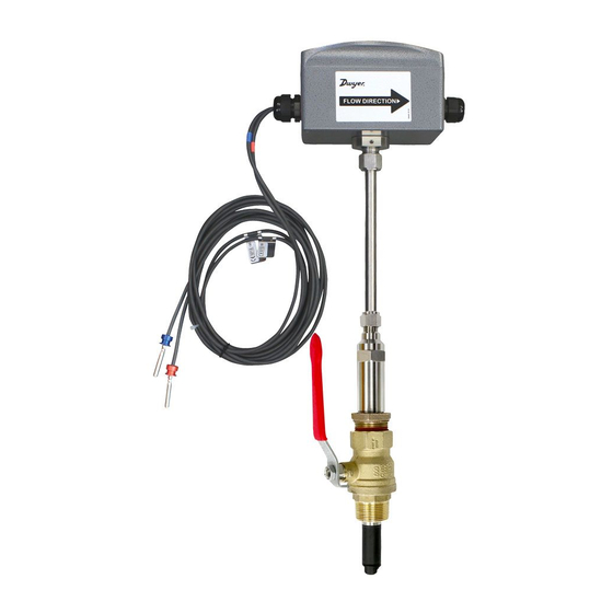
Series IEFB Insertion Thermal Energy Meter
Specifications - Installation and Operating Instructions
IEFB-X-X-TXX
IEFB-X-X-TXX
Shown with
A-IEF-VLV-BR
accessory valve
The Series IEFB is a field-adjustable insertion thermal energy meter that uses
electromagnetic technology to accurately and reliably measure fluid velocity and
energy consumption. The high accuracy IEFB is adjustable to fit pipe sizes from 4 to
10˝ (100 to 250 mm), while the standard accuracy IEFB fits pipe sizes 4 to 36˝ (100 to
900 mm). The flowmeter is simple to install and incorporates a temperature meter and
an energy calculator into a single unit. The LCD display provides precise readings of
the meter's values, including temperature and energy consumption, making it ideal for
installation on chillers, boilers, and other heating and cooling applications. The meter's
high measuring accuracy and long lifetime keeps annual system operating costs at
a minimum. In addition, it offers several output options, including selectable BACnet
MS/TP or Modbus
RTU communications protocol over 2-wire RS-485 and standard
®
analog, frequency, and alarm outputs.
FEATURES/BENEFITS
• Flexible, field configurable setup displays (-LCD integral option or remote accessory
A-IEF-DSP) accommodate a variety of application configurations. Application
information is display selectable and includes pipe size, pipe material, liquid type,
analog output, pulse/frequency output, alarm outputs, communication outputs,
damping, and calibration factor
• High performance accuracy is maintained through changes in temperature, density
and/or viscosity
• The Setup Wizard and installation tool are simple to use, providing quick and precise
installation
• Accessory setup kit A-IEF-KIT comes with a thickness gage and measuring tape to
ensure exact installation depth
• The meter has no moving parts and electrodes that discourage fouling, which gives
the meter a long lifecycle and minimizes the need for maintenance
• Hot-tap isolation valve accessories allow for easy installation and removal in
operational systems without system downtime
APPLICATIONS
• Monitoring chiller cooling output performance
• Industrial boiler heating performance
• Energy efficiency monitoring
• Optimization of heat energy performance
• Commercial and residential heat energy consumption and metering
• District heating and cooling monitoring
• Energy cost allocation monitoring
DWYER INSTRUMENTS, INC.
P.O. BOX 373 • MICHIGAN CITY, INDIANA 46360, U.S.A.
-LCD option
A-IEFB-THW-XX
Hot-tap thermowells for model
IEFB-X-X-RXX (2), shown
with A-IEFB-VLV-BR-1
accessory valve
THERMOWELL MODEL CHART
Model
A-IEFB-THW-4
A-IEFB-THW-6
8-23/64 [212.2]
5-53/64
[148.0]
21-1/64
[533.6]
22-1/64
[559.0]
61/64
[24.1]
A-IEFB-THW-XX (2)
SPECIFICATIONS
Service: Compatible clean or dirty non
coating, conductive liquids.
Range: 0 to 20 ft/s (0 to 6 m/s).*
Wetted Materials: Body shaft/fitting: 316
SS; Electrodes: 316 SS; Electrode cap:
Polymer/polystyrene; O-ring: Silicone;
Thermowells: 304 SS.
BTU Accuracy per EN1434/ASTM
E3137/CSA C900.1-13: High Accuracy
Units: Class 2 for 2 to 20 ft/s (0.6 to 6
m/s)**; Standard Accuracy Units: Class 3
for 6.5 to 20 ft/s (2 to 6 m/s)**.
Flow Sensor Accuracy: High Accuracy
Units: ±0.5% of reading at calibrated
velocity, ±1% of reading from 2 to 20 ft/s
(0.6 to 6 m/s) ±0.02 ft/s (±0.006 m/s) at <
2 ft/s (0.6 m/s); Standard Accuracy Units:
±1% FS.
Temperature Accuracy: Class B ±(0.30
+ 0.005*t)°C per EN60751.
Differential Temperature Accuracy: Et
= ±(0.5 +3*ΔΘmin/ΔΘ) % per EN1434.
Calculator Accuracy: Ec = ±(0.5
+ΔΘmin/ΔΘ) % per EN1434.
Temperature Compensation: 140 to
220°F (60 to 104.4°C) < 2% error over
±30°F (-1.1 °C) change, 40 to 70°F
(4.4 to 21.1°C) < 2% error over ±10°F
(-12.2°C) change.
Temperature Limits: Ambient: -20 to
160°F (-29 to 71°C), -LCD -4 to 158 °F
(-20 to 70 °C); Process: 15 to 250°F (-9
to 121°C); Storage: -40 to 185°F (-40 to
85°C).
Process Connection: Flowmeter: 1˝
NPT or BSPT with accessory full port ball
valve options; Thermowell: (2) 1/2˝ NPT
or BSPT thermowell with 1˝ full port ball
valve options.
Pressure Limit: 400 psi (27.6 bar) @
100°F (37.8°C).
Pressure Drop: < 0.1 psi at 12 ft/s in 4˝
(<0.01 bar at 3.7 m/s in 100 mm) and
larger pipe.
Outputs: (1) Analog: 4-20 mA, 0-5 V,
0-10 V or 2-10 V (display selectable);
(1) Pulse/Frequency: 0-15 V peak
pulse, 0-500 Hz or scalable pulse output
(display selectable); (2) Alarm: Empty
pipe detection or minimum/maximum
velocity, (display selectable) & Reverse
flow output indication.
*For max flowrates >10 ft/s (3 m/s) order option -CC.
** Verified at standard temperature 73.4°F (23°C) refer to listed standards for
detailed accuracy formulations.
Modbus
1
Phone: 219/879-8000
Fax: 219/872-9057
Bulletin F-IEFB
A
B
4-11/16˝ (119.0 mm)
5-25/32 (146.8 mm)
6-11/16˝ (169.8 mm)
7-25/32 (197.6 mm)
5-53/64
[148.0]
4-51/64
[121.9]
13-25/32
[350.0]
12-11/16
B
A
[322.2]
IEFB-X-X-RXX (2)
Power Requirements: 12-42 VDC, .25 A
@ 24 VDC; 12-36 VAC.
Electrical Connection: Removable
terminal blocks, (2) model selectable 1/2˝
female NPT conduit connection, (2) PG
16 gland or (2) PG 16 gland with 10 ft (3
m) 9 conductor 22 AWG plenum rated
cables, accessory cable lengths up to
200 ft (61 m) optional.
Display (-LCD option): 2 x 2˝ (50 x 50
mm) graphic LCD with backlight.
Conductivity: >20 microsiemens.
Enclosure Material: Powder coated die
cast aluminum.
Enclosure Ratings: NEMA 6P (IP68)
(Non display models); NEMA 4X (IP66)
(-LCD option).
Agency Approvals: BTL.
COMMUNICATIONS (-COM OPTION)
Type: BACnet MS/TP or Modbus
RTU communication protocol (default
disabled, display selectable).
Supported Baud Rates: 9600, 19200,
38400, 57600, 76800, or 115200 bps
(display selectable).
Device Load: 1/8 unit load.
ADDITIONAL SPECIFICATIONS
Applicable Pipe Material: Most popular
plastic and metal pipes; i.e. Carbon steel,
SS, copper, UPVC/PVDF, galvanized
steel, mild steel, and brass.
Applicable Pipe Size: 4 to 36˝ (100 to
900 mm), model dependent. See model
chart.
Diameter Length Requirements: >10
upstream, >5 downstream.
Temperature Resistance: Matched 4
wire platinum RTD's.
Relative Humidity: 10 to 90% non-
condensing.
Output Impedance: 4-20 mA: 536 Ω;
5V: 500 Ω; 10V: 1.27k Ω.
is a registered trademark of Schneider Automation, Inc.
®
www.dwyer-inst.com
e-mail: info@dwyermail.com
®
Advertisement

Related Manuals for Dwyer Instruments IEFB Series


Summary of Contents for Dwyer Instruments IEFB Series
- Page 1 ** Verified at standard temperature 73.4°F (23°C) refer to listed standards for detailed accuracy formulations. Modbus is a registered trademark of Schneider Automation, Inc. ® DWYER INSTRUMENTS, INC. Phone: 219/879-8000 www.dwyer-inst.com P.O. BOX 373 • MICHIGAN CITY, INDIANA 46360, U.S.A. Fax: 219/872-9057...
-
Page 2: Model Chart
Safety Information MODEL CHART Example IEFB -L N -CND -R10 -LCD IEFB-LN-CND-R10-LCD WARNING Series IEFB Insertion thermal energy meter Accuracy Standard accuracy <10˝ (250 mm) • Only qualified professionals equipped with the necessary required trade skills pipe; 1% FS should install, remove or service this product. Failure to follow the Standard accuracy >10˝... - Page 3 RECOMMENDED TOOLS IEFB THERMAL ENERGY METER INSTALLATION • (2) 12˝ (300 mm) adjustable wrenches FLOWMETER INSTALLATION • (1) 12˝ (300 mm) pipe wrench 1. To prepare the meter for installation, mount the provided alignment scale to the side of the meter using the two captured thumbscrews, finger tighten only. Be SETUP sure to orient the alignment scale as shown in Figure 5 below.
- Page 4 3. Plug the other end of the cable into the bottom of A-IEF-DSP or A-IEF-KIT. Sensor Alignment Orient the keying feature/tab as shown: A depth and flow alignment installation tool is provided to ensure proper depth insertion and flow alignment. To set the insertion depth, verify the alignment scale is set to the alignment scale value recorded previously as shown in figure 9 below.
- Page 5 Hot Tap Thermowell Sensor Depth 1. Insert the thermowell into the process collet (3) by loosening compression nut (2). Screw into process valve (4) open the valve by turning valve handle (5). 2. Fully insert thermowell to maximum depth. a. If thermowell makes contact with pipe ID, retract 1/4˝ (65 mm). 3.
-
Page 6: Power Supply
RTD INSTALLATION GROUNDING The Series IEFB is provided with a matched pair of temperature sensors. These Metallic Pipe temperature sensors must be wired to the IEFB and properly installed into the For proper operation, the IEFB must be earth grounded. accessory thermowells. -
Page 7: Wiring Diagram
WIRING DIAGRAM Cable Terminal # Wire Color Description Note Power Supply Positive Connect to +24VDC or VAC transformer Black Power Supply Common Connect to 24VDC/VAC common Shield If used - Application Dependant Shield If used - Application Dependant External Earth/Chassis Ground Analog Current Output Brown (+) Analog current output... - Page 8 Figure 19: PCBA Figure 20: Wiring diagram...
- Page 9 IEFB SETUP Determining IEFB probe insertion depth for models without a display IEFB FLOWMETER SETUP For models without a display, the following formulas allow for calculating the alignment Determining IEFB probe insertion depth for models with a display scale value. Pipe wall thickness charts are also included on the next page. Use the Series IEFB insertion thermal energy meter with -LCD display option or A-IEF- Pipes <12 in (250 mm) diameter: 7.1625-1/2*D DSP to calculate the probe insertion depth.
-
Page 10: Wall Thickness
WALL THICKNESS Carbon Steel Pipe Diameter (in) DN (mm) SCH5 (in) SCH5 (mm) SCH10 (in) SCH10 (mm) SCH40 (in) SCH40 (mm) SCH80 (in) SCH80 (mm) 114.30 0.083 2.110 0.120 3.050 0.237 6.020 0.337 8.560 5.563 141.30 0.109 2.770 0.134 3.400 0.258 6.550 0.375... - Page 11 WALL THICKNESS Carbon Steel Pipe Diameter (in) DN (mm) SCH5 (in) SCH5 (mm) SCH10 (in) SCH10 (mm) SCH40 (in) SCH40 (mm) SCH80 (in) SCH80 (mm) 114.30 0.083 2.110 0.120 3.050 0.237 6.020 0.337 8.560 5.563 141.30 0.109 2.770 0.134 3.400 0.258 6.550 0.375...
- Page 12 Printing out configuration values Removing Series IEFB Insertion Thermal Energy Meter After installation is complete, a table of configuration values can be printed to insert 1. To remove the meter from an installation without a valve, depressurize the pipe into one of the hanging plastic envelopes for future reference. The housing cover/ and skip to step 4.
- Page 13 Network Termination Jumper BACNET On the terminal block PCBA there is a jumper, J1 (see Figure 24), that enables or BACnet Object Overview disables a network termination resistor as defined below: Supported BACnet Objects When the network jumper is in the ON position there is a 120 ohm termination resistor in place.
- Page 14 Object Name “Series IEF 607xxx” “Series IEFB 607xxx” CharacterString(40) Read/Write Object Type DEVICE(8) BACnetObjectType Read System Status Property List BACnetDeviceStatus Read Vendor Name “Dwyer Instruments, Inc.” CharacterString Read Vendor Identifier Unsigned Read Model Name “IEF-??-??-COM” CharacterString Read Firmware Revision “?.?” CharacterString...
- Page 15 The default object identifier is 607xxx, where xxx is replaced by the MS/TP MAC address set in the Network Address menu. The object identifier value will change as the MS/TP MAC address changes. However, if a specific object identifier is written via BACnet, then that value is stored and changes to the MS/TP MAC address will no longer affect the object identifier.
- Page 16 Analog Input – Outlet Temperature Property Default Value Property Data Type Access Object Identifier BACnetObjectIdentifier Read Object Name "Outlet Temperature" CharacterString Read Object Type ANALOG_INPUT (0) BACnetObjectType Read Present Value Current reading Real Read Status Flags BACnetStatusFlags Read Event State Normal (0) BACnetEventState Read...
- Page 17 Analog Value – Total Flow Property Default Value Property Data Type Access Object Identifier BACnetObjectIdentifier Read Object Name "Total Flow" CharacterString Read Object Type ANALOG_VALUE (2) BACnetObjectType Read Present Value Current reading Real Read Status Flags BACnetStatusFlags Read Event State Normal (0) BACnetEventState Read...
- Page 18 Analog Value – Heat Energy Property Default Value Property Data Type Access Object Identifier BACnetObjectIdentifier Read Object Name "Heat Energy" CharacterString Read Object Type ANALOG_VALUE (2) BACnetObjectType Read Present Value Current reading Real Read Status Flags BACnetStatusFlags Read Event State Normal (0) BACnetEventState Read...
- Page 19 Analog Value – YTD Max Power Property Default Value Property Data Type Access Object Identifier BACnetObjectIdentifier Read Object Name "YTD Max Power" CharacterString Read Object Type ANALOG_VALUE (2) BACnetObjectType Read Present Value Current reading Real Read Status Flags BACnetStatusFlags Read Event State Normal (0) BACnetEventState...
- Page 20 Analog Value – Inlet YTD Average Temperature Property Default Value Property Data Type Access Object Identifier AV13 BACnetObjectIdentifier Read Object Name "Inlet YTD Average Temperature" CharacterString Read Object Type ANALOG_VALUE (2) BACnetObjectType Read Present Value Current reading Real Read Status Flags BACnetStatusFlags Read Event State...
- Page 21 Analog Value – Ethylene Glycol Concentration Property Default Value Property Data Type Access Object Identifier AV17 BACnetObjectIdentifier Read Object Name “Ethylene Glycol Concentration” CharacterString Read Object Type ANALOG_VALUE (2) BACnetObjectType Read Present Value Real Read/Write Status Flags BACnetStatusFlags Read Event State Normal (0) BACnetEventState Read...
- Page 22 Binary Value – Reset Energy Statistics Property Default Value Property Data Type Access Object Identifier BACnetObjectIdentifier Read Object Name “Reset Energy Statistics” CharacterString Read Object Type BITSTRING_VALUE (39) BACnetObjectType Read Present Value Inactive (0) BACnetBinaryPV Read/Write Status Flags BACnetStatusFlags Read Event State NORMAL (0) BACnetEventState...
- Page 23 Date Value – YTD Max Power Date Property Default Value Property Data Type Access Object Identifier BACnetObjectIdentifier Read Object Name “YTD Max Power Date” CharacterString Read Object Type DATE_VALUE (42) BACnetObjectType Read Present Value Current Value Date Read Status Flags BACnetStatusFlags Read Event State...
- Page 24 Date Value – YTD Max Power Date Property Default Value Property Data Type Access Object Identifier PIV1 BACnetObjectIdentifier Read Object Name “Energy Hour Counter” CharacterString Read Object Type POSITIVE_INTEGER_VALUE (48) BACnetObjectType Read Present Value Current value Date Read Status Flags BACnetStatusFlags Read Event State...
- Page 25 MODBUS ® Modbus Functions ® The device supports the following functions Function Name Function Code Read Holding Registers Read Input Registers Write Single Register Write Multiple Registers Modbus Registers ® Input Registers The String data type is read as a Register Description Data Type...
- Page 26 Holding Registers Setting the Date and Time: The IEFB contains a battery backed real-time clock. Current date and time can be set Register Description Data Type Range with the current date and current time registers. Note, however, that the date and time will not be updated until a value of 1 is written to the Update Date &...
- Page 27 Multi-Address Support POWER UNIT VALUES Multi-Address support allows a register to be read or written to using different byte Value Unit orientations specified by the address range. For example, input register 0003 can also be read at 2003, 4003 and 6003 with different byte orientations as listed in Table 7. Watt (W) Kilowatt (kW) Registers that do not have multi-address support are only available in Big-Endian byte...
-
Page 28: Firmware Version
Electronic Control Setup -LCD Display Option or A-IEF-DSP Accessory Main Configuration Wizard Basic information 1. Language Selection: 1. Turn on the power to the Display/Menu. • At the Language Screen select the Language: • The menu default language is English. At power ON, the Dwyer Logo, Serial Number and Firmware NOTICE •... - Page 29 5. Mass Flow Unit Menu: Pipe Configuration Wizard • This option determines how the mass flow is displayed. 1. Pipe Material Menu: • The Default is pounds-mass-per-hour. • This option helps determine the pipe dimensions as well as account for different material properties.
- Page 30 3. Install Kit Menu (Standard): 6. Liquid Type Menu: A. Nominal Pipe Size Menu • This option specifies the process liquid to be measured. • Select the diameter of the installation pipe from the list of standard pipe • If Ethylene Glycol is selected, the next menu will allow the concentration to diameters.
- Page 31 9. Energy Meter Configuration Wizard D. Process Pressure Menu: A. Flow Meter Location Menu: ◦Input the process pressure inside the pipe. ◦Select the location of the flow meter in the inlet or outlet pipe. ◦Default: 232.060 PSI. ◦Default: Inlet. E. Energy Meter Summary Display: ◦This screen shows a summary of the settings entered in the Energy Meter configuration wizard.
- Page 32 12. Analog Output High Menu: 2. Pulse/Frequency Output Menu: • This value determines the process value at which the analog output will be • This option determines the type of digital output from the meter. at maximum (e.g. 20 mA, 10 V, 5 V). •...
- Page 33 D. Frequency Output High Menu: 5. Empty Alarm Setup Menu ◦ This value determines the process value at which the frequency output • This screen displays a summary of the Alarm output configuration. The will be at maximum (500Hz). image displayed indicates the alarm type is Empty Pipe, meaning that ◦...
- Page 34 Communication Configuration Wizard 7. Serial Parity Menu (Modbus Communications Protocol Only): ® 1. If Continue is selected, the next menu displayed will be the Communication • This option sets the serial parity on the RS-485 bus. configuration wizard. • Default: Even. 2.
- Page 35 Process Value Display: Device Information • This display is the default view after power on of a configured meter or when the • A list of all setting summaries. Use RIGHT and LEFT to move between Save & Exit option is selected from the Setup Wizard. the various summary pages.
- Page 36 Date & Time Setup: 5. Set Local Time: 1. This menu sets up the date and time on the IEFB. •. This option sets the local time in HH:MM:SS format. • Select Time Format to set time. • Use the up/down arrow keys to input the hours, minutes, seconds, and AM/PM (12 hour format).
- Page 37 Damping Indicator Display Setup • This value determines the amount of time the velocity is averaged. The • If a remote indicator display is being used, select which values should be display value will reach 99% of the measured value within this time. displayed.
-
Page 38: Troubleshooting Guide
Troubleshooting Guide STATUS LED A status blink code is conveyed by the blinking of the status LED (Figure 26) using the following parameters. A blink is defined as the LED is ON for 200ms followed by the LED being OFF for 200ms. -
Page 39: Maintenance/Repair
MAINTENANCE/REPAIR Upon final installation of the Series IEFB, no routine maintenance is required. If recalibration is desired the unit must be returned to Dwyer Instruments, Inc. to be calibrated. Contact customer service to receive a Return Goods Authorization number before shipping you product back for calibration. The Series IEFB is not field serviceable and should be returned if repair is needed. - Page 40 __________________________________________________________________________________________________________________________________________ __________________________________________________________________________________________________________________________________________ __________________________________________________________________________________________________________________________________________ __________________________________________________________________________________________________________________________________________ __________________________________________________________________________________________________________________________________________ __________________________________________________________________________________________________________________________________________ __________________________________________________________________________________________________________________________________________ __________________________________________________________________________________________________________________________________________ __________________________________________________________________________________________________________________________________________ __________________________________________________________________________________________________________________________________________ ©Copyright 2019 Dwyer Instruments, Inc. Printed in U.S.A. 8/19 FR# 444531-00 DWYER INSTRUMENTS, INC. Phone: 219/879-8000 www.dwyer-inst.com P.O. BOX 373 • MICHIGAN CITY, INDIANA 46360, U.S.A. Fax: 219/872-9057 e-mail: info@dwyermail.com...
Need help?
Do you have a question about the IEFB Series and is the answer not in the manual?
Questions and answers