Table of Contents
Advertisement
Quick Links
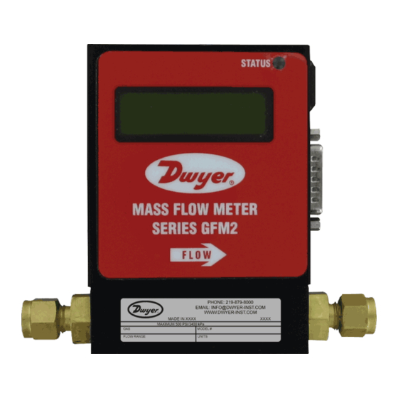
SERIES GFM2
GAS MASS FLOW METER
±1% FS, Programmable Relays
The SERIES GFM2 Gas Mass Flow Meters is an ideal choice for the measurement of
flow rates of a wide variety of gases. Unit can be calibrated for a variety of gases with
user selectable 0 to 5 VDC or 4 to 20 mA and two relay outputs and programmable
totalizer that indicates total gas quantity.
FEATURES/BENEFITS
• Utilizes a straight tube sensor with a restrictor flow element to provide a high ±1% FS
accuracy and ±0.25% FS repeatability
• Gas flow can be displayed in 23 different engineering units on an optional 2x16
character LCD display with internal conversion factors for up to 32 gases
• Digital RS-232 or RS-485 interfaces allow for easy communication and for multi-drop
capability of up to 256 units (RS-485 only)
• User-friendly interface allows for the programming of high and low gas flow alarms,
along with two user-programmable electromechanical SPDT relays with latch options
• Stores calibration information for up to 10 different gases, internal or user-specific
K-factors
• Automatic sensor zero offset adjustment (via digital interface or local push button)
• NIST traceable certificate included
• Self-diagnostic tests
APPLICATIONS
• Gas flow measurement
• Gas flow control
• Operating pumps and valves
• Process equipment
• Vacuum processes
• Glass and metal coating
• Film deposition
MODEL CHART
Example GFM2 -AIR
-010 -A -V -A -N -A -2 GFM2-AIR-010-A-V-A-N-A-2
Series
GFM2
Specialty
AIR
Gas &
AR
K-Factor
C2H2
C3H8
C4H10
CH4
CO
CO2
HF
HE
H2
N2
NH3
O2
SO2
Body
010
Size
050
100
Body
A
Material
S
Seal
Material
Fittings
Display
Output
Signal
Digital
Interface
Gas mass flow meter
Air 1.0000
Argon 1.4573
Acetylene 0.5829
Propane 0.3500
Butane 0.2631
Methane 0.7175
Carbon monoxide 1.0000
Carbon dioxide 0.7382
Hydrogen fluoride 0.9998
Helium 1.4540
Hydrogen 1.0106
Nitrogen 1.0000
Ammonia 0.7310
Oxygen 0.9926
Sulfur dioxide 0.6900
Low flow
Medium flow
High flow
Aluminum
Stainless steel: Body size = 010
Body size = 050
Body size = 100
V
Fluoroelastomer
B
Buna-N
E
EPR
T
PTFE
A
1/4˝ compression (low)
B
1/8˝ compression (medium)
D
3/8˝ compression (high)
N
No display
L
LED display
A
0 to 5 VDC
B
4 to 20 mA
2
RS232
5
RS485
9
PROFIBUS
1-1/8
[28.70]
3-5/32 [80.16]
5-5/16 [134.88]
SPECIFICATIONS
Service: Clean gases compatible with wetted parts.
Wetted Materials: GFM2-X-X-A: Anodized aluminum, brass, 316 SS
fluoroelastomer O-rings; GFM2-X-X-S: 316 SS, and fluoroelastomer O-rings;
Buna-N, EPR and PTFE O-rings optional.
Accuracy: ±1% FS.
Repeatability: ±0.25% FS.
Response Time: 2 seconds to within ±2% of actual flow.
Output Signal: Linear 0 to 5 VDC (3000 Ω min. load impedance) and 4 to 20 mA
(500 Ω max. loop resistance).
Relay Rating: 1 A @ 24 VDC.
Max. Particulate Size: 5 microns.
Temperature Limits: 32 to 122°F (0 to 50°C).
Power Supply: 11 to 26 VDC.
Process Connections: 1/8˝ compression fitting for flow rates ≤ 10 L/min; 1/4˝ for ≤
50 L/min; 3/8˝ for ≤ 100 L/min.
Display: 2 x 16 character LCD (optional).
Pressure Limits: 500 psig (34.5 bar).
Leak Integrity: 1 x 10
smL/sec of helium.
-9
Weight: 1.05 lb (0.48 kg).
MAXIMUM FLOW RANGE (l/min)
Body Size AIR AR
010
10
050
50
100
100
MAXIMUM FLOW RANGE (l/min)
Body Size CO
010
5
050
30
100
60
FLOW RANGES
ml/min
l/min
10
2
20
5
50
10
100
20
200
30
500
40
1000
50
60
80
100
Note: Specify flow
range at time of order
ACCESSORIES
Model
Description
A-110NA12 110 VAC power supply, 12 VDC with
communication interface branch
USA: California Proposition 65
WARNING: Cancer and Reproductive Harm - www.P65Warnings.ca.gov
DWYER INSTRUMENTS, INC. | www.dwyer-inst.com
4-29/64
[112.97]
PROCESS CONNECTION
[COMPRESSION FITTINGS ATTACHED]
C
H
C
H
C
H
CH
CO
2
2
3
8
4
10
4
10
5
2
2
5
10
50
20
10
5
30
50
100
50
30
20
60
100
HE
H
N
NH
O
SO
2
2
2
3
2
10
10
10
5
10
5
50
50
50
30
50
30
100
100
100
60
100
60
2
323
Advertisement
Table of Contents

Related Manuals for Dwyer Instruments GFM2 Series


Summary of Contents for Dwyer Instruments GFM2 Series
- Page 1 A-110NA12 110 VAC power supply, 12 VDC with LED display communication interface branch Output 0 to 5 VDC Signal 4 to 20 mA Digital RS232 Interface RS485 PROFIBUS USA: California Proposition 65 WARNING: Cancer and Reproductive Harm - www.P65Warnings.ca.gov DWYER INSTRUMENTS, INC. | www.dwyer-inst.com...
- Page 2 Bulletin F-GFM2 Series GFM2 Digital Mass Flow Meter Installation and Operating Instructions DWYER INSTRUMENTS, INC. Phone: 219/879-8000 www.dwyer-inst.com P.O. BOX 373 • MICHIGAN CITY, INDIANA 46360, U.S.A. Fax: 219/872-9057 e-mail: info@dwyer-inst.com...
-
Page 3: Table Of Contents
TABLE OF CONTENTS 7. Calibration Procedures ......... .8 7.1 Flow Calibration . -
Page 4: Unpacking The Gfm2 Flow Meter
GFM2 Mass Flow Meters are equipped with either calibrated 0 to 5 VDC (0 to 10 copy of any damage report to your distributor or Dwyer Instruments, Inc directly. VDC optional) or calibrated 4 to 20 mA output signals (jumper selectable). This When unpacking the instrument please make sure that you have all the items linear output signal represents 0 to 100% of the flow meter's full scale range. -
Page 5: Principle Of Operation
Additionally, the GFM2 Mass Flow Meter incorporates a precision analog PIN GFM2 FUNCTION microcontroller and non-volatile memory that stores all hardware specific variables Common, Signal Ground and up to 10 different calibration tables. The flow rate can be displayed in 23 For Pin 2 (4 to 20 mA return) different volumetric or mass flow engineering units. -
Page 6: Operating Instructions
Flow Rates NOTICE During the first 6 minutes of the initial powering of the GFM2 Flow rates are stated for Nitrogen at STP conditions [i.e. 70°F (21.1°C) at 1 atm]. transducer, the status LED will emit a constant amber light. For other gases use the K factor as a multiplier from APPENDIX III. -
Page 7: Gas Table Settings
5.3.2 Gas Table Settings Latch Mode - Controls Latch feature when Relays are assigned to Alarm event. The GFM2 Mass Flow Meter is capable of storing calibration data for up to 10 Following settings are available: different gases. Digital interface commands are provided to: 0 - Latch feature is disabled for both relays - get currently active Gas Table number and Gas name 1 - Latch feature is enabled for Relay#1 and disabled for Relay#2... -
Page 8: Self Diagnostic Alarm
If alcohol is used for cleaning, allow time for drying. 5.4 Analog Output Signals Configuration GFM2 series Mass Flow Meters are equipped with calibrated 0 to 5 VDC and 4 to Inspect the flow path inside the transducer for any visible signs of contaminant. If 20 mA output signals. -
Page 9: Calibration Procedures
Any alteration of the gas linearization table will 7.1 Flow Calibration VOID calibration warranty supplied with instrument. Dwyer Instruments' Flow Calibration Laboratory offers professional calibration support for Mass Flow Meters using precision calibrators under strictly controlled Gas flow calibration parameters are separately stored in the Gas Dependent conditions. -
Page 10: Analog Output Calibration Of Gfm2 Mass Flow Meters
7.3 Analog output Calibration of GFM2 Mass Flow Meters 7.3.3 Gas Flow 4 to 20 mA Analog Output Calibration GFM2 series Mass Flow Meters are equipped with 1. Install jumpers J7A, J7B and J7C on the PC board for 4 to 20 mA output (see calibrated 0 to 5 Vdc and 4 to 20 mA output signals. -
Page 11: Ascii Commands Set
After assigning the new address, a device will accept commands with the new NOTICE Address 00 is reserved for global addressing. Do not assign, address. the global address for any device. When command with global address is sent, all devices on the RS-485 bus execute the command but do not NOTICE Do not assign the same RS-485 address for two or more reply with an acknowledge message. - Page 12 Command Command Argument 1 Argument 2 Argument 3 Argument 4 Response Name Description 1 (relay 1) R1N or R2N Relay Action Assigns action of the two SPDT 2 (relay 2) R1T or R2T relays. The coil is energized when the condition specified by R1H or R2H R1L or R2L an Argument 2 becomes true.
-
Page 13: Troubleshooting
Command Command Argument 1 Argument 2 Argument 3 Argument 4 Response Name Description R (read timer) <Value> (in Hours) Maintenance Hours since last time unit was C (set timer to zero) Timer calibrated. Full Scale Returns the full scale rated flow in <Value>... -
Page 14: Technical Assistance
9.3 Technical Assistance used to relate the calibration of the actual gas to the reference gas. Dwyer Instruments will provide technical assistance over the phone to qualified repair personnel. Please have your Serial Number and Model Number ready when you call. -
Page 15: Appendix Igfm2 Eeprom Variables
APPENDIX I Dwyer GFM2 EEPROM Variables Rev. A0 ® Gas Independent Variables Indication Data Type Notes BlankEEPROM char[10] Do not modify. Table Revision. [PROTECTED] SerialNumber char[20] Serial Number [PROTECTED] ModelNumber char[20] Model Number [PROTECTED] SoftwareVer char[10] Firmware Version [PROTECTED] TimeSinceCalHr float Time since last calibration in hours Options1... -
Page 16: Internal User Selectable Gas Factor Table (Internal "K" Factors)
Calibration Table Gas Dependent Variables Index Name Data Type Notes GasIndentifier char[20] Name of Gas [If not calibrated = ‘Uncalibrated’] FullScaleFlow float Full Scale Range in l/min StdTemp float Standard Temperature StdPressure float Standard Pressure StdDensity float Gas Standard Density CalibrationGas char[20] Name of Gas used for Calibration... -
Page 17: Appendix Iii Gas Factor Table ("K" Factors)
APPENDIX III - Gas Factor Table (“K Factors”) NOTICE K-factors at best are only an approximation. K factors should not be used in applications that require accuracy better than ±5 to 10%. Density K-Factor (g/l) Index Actual Gas Relative to N (Cal/g) 1.162 Acetylene C... - Page 18 K-Factor Density Index Actual Gas Relative to N (Cal/g) (g/l) Hexafluoroethane C (Freon-116) .2421 .1834 6.157 Hexane C .1792 .3968 3.845 Hydrogen H -1 (<10-100 L) 1.0106 3.419 .0899 Hydrogen H -2 (>10-100 L) 1.35 3.419 .0899 Hydrogen H -3 (>100 L) 3.419 .0899 Hydrogen Bromide HBr...
-
Page 19: Appendix Iv Component Diagram
APPENDIX IV - Component Diagram Top Component Side Bottom Component Side Page 18... -
Page 20: Appendix V Dimensional Drawings
APPENDIX V Dimensional Drawings 3-5/32 1-1/8 [80.16] [28.70] 4-29/64 [112.97] MASS FLOW METER SERIES GFM2A FLOW 5-5/16 [134.88] PROCESS CONNECTION (COMPRESSION FITTINGS ATTACHED) APPENDIX VI MAINTENANCE/REPAIR Upon final installation of the Series GFM3, no routine maintenance is required. The Series GFM3 is not field serviceable and should be returned if repair is needed. Field repair should not be attempted and may void warranty (See 1.3). - Page 21 Page 20 ©Copyright 2013 Dwyer Instruments, Inc. Printed in U.S.A. 5/13 FR# RA-444052-00 DWYER INSTRUMENTS, INC. Phone: 219/879-8000 www.dwyer-inst.com P.O. BOX 373 • MICHIGAN CITY, INDIANA 46360, U.S.A. Fax: 219/872-9057 e-mail: info@dwyer-inst.com...
Need help?
Do you have a question about the GFM2 Series and is the answer not in the manual?
Questions and answers