Hatz Diesel 2G40 Instruction Book
Hide thumbs
Also See for 2G40:
- Translation of the original instruction manual (52 pages) ,
- Workshop manual (284 pages) ,
- Translation of the original instruction book (33 pages)

Related Manuals for Hatz Diesel 2G40


Summary of Contents for Hatz Diesel 2G40
- Page 1 INSTRUCTION BOOK 2G40 2G40 H 433 316 05-USA-EPA IV-CARB 12.07-0.05 Printed in Germany...
- Page 2 A new HATZ Diesel engine - working for you This engine is intended only for the purpose determined and tested by the manufacturer of the equipment in which it is installed. Using it in any other manner contravenes the intended purpose.
-
Page 3: Table Of Contents
Contents Page Important notes on safe operation of the engine Description of the engine General information 3.1. Technical data 3.2. Transport 3.3. Instructions for installation 3.4. Load on engine 3.5. EPA / CARB-type plates 3.6. Emission-related installation instructions Operation 4.1. Before initial start-up 4.2. -
Page 4: Important Notes On Safe Operation Of The Engine
1. Important notes on safe operation of the engine HATZ diesel engines are economical, stronly built and long-lasting. They are therefore frequently chosen for commercially and industrially operated equipment and machinery. Since the engine forms part of the finished equipment or machine, its manufacturer will take all the applicable safety regulations into account. - Page 5 Important notes on safe operation of the engine – Stop the engine before performing any maintenance, cleaning- or repair work. – Stop the engine before refuelling. Never add fuel near a naked flame or a source of sparks. Don't smoke. Don't spill fuel. –...
-
Page 6: Description Of The Engine
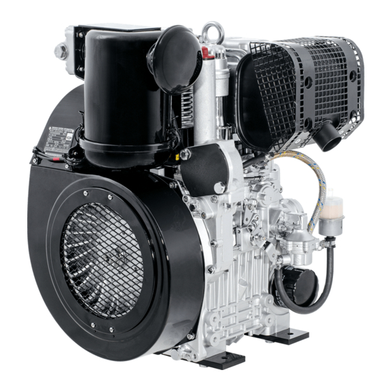
Description of the engine Fig. 1 1 Fuel line (feed pump – 12 Oilbath air cleaner 25 Oil drain plug fuel-injection pump) 13 Oil pressure switch 26 Guard 2 Air deflector 14 Rainproof cap 27 Air guide housing 3 Oil dipstick 15 Oil filler cap 28 Separable connector 4 Fuel return line... -
Page 7: General Information
General remarks 3.1. Technical data Type 2G40 / 2G40 H Design Air-cooled four-stroke diesel engine Combustion system Direct injection Number of cylinders Bore/stroke 92 / 75 Displacement cm³ Engine oil content 2.5 excl. sump incl. filter renewal l. approx. 3.0 incl. sump Difference between „max“... -
Page 8: Transport
3.2. Transport The lifting eyebolt provided as stand- The permitted loads and elements on ard equipment is intended for safe the speed adjusting lever and the stop movement of the engine with its auxiliaries. lever should be observed as an exess can lead Its maximum load capacity is 150 kg. -
Page 9: Epa / Carb-Type Plates
3.5. EPA/CARB-type plates and For any offer as well as spare parts orders it is necessary to mention the following data (also fuel label see spare parts list, page 1): There are two EPA/CARB- type plates applied for ➁ engine type / spec. the identification of the engine. -
Page 10: Emission-Related Installation Instructions
Fuel label Operation 4.1. Before initial start-up Engines are normally delivered without fuel and oil. LOW SULFUR FUEL OR ULTRA 4.1.1. Engine oil LOW SULFUR FUEL ONLY Oil quality Qualified are all trademark oils which fulfil at least one of the following specifications: ACEA –... - Page 11 When adding oil or checking the level, the en- If a cyclone-type dust trap is fitted, make sure gine must be in a horizontal position. that the dust outlet is pointing in the correct direction (fig. 7). – Fill the oil tank up to mark „1“ with engine oil. –...
-
Page 12: Starting The Engine
4.2. Starting the engine Do not run the engine in closed or badly ventilated rooms – danger of poisoning! Before starting the engine, make sure that no one is within the danger area near the engine or the machinery it is driving, and that all the necessary guards are installed. - Page 13 – As soon as the engine runs, release the start key. It must return to position I by itself and remain in this position during operation. The battery charge telltale and oil pressure warning must go out immediately after start- ing.
-
Page 14: Stopping The Engine
4.3. Stopping the engine Stop Start Start Stop – Move speed control lever „1“ back to the The charge 2 and oil pressure pilot lamps 3 „STOP“ position. come on. – On engines with the lower idling speed out of –... -
Page 15: Maintenance
Maintenance The engine must be stopped before any maintenace work is attempted. Comply with legal requirements when handling and disposing of old oil, filters and cleaning materials. Keep the engine's key and starting handle out of reach of unauthorized persons. To immobilize engines with an electric starter, disconnect the negative battery terminal. - Page 16 The above maintenance chart is supplied with For new or reconditioned engines, the following every engine. This label should be affixed to the must always be carried out after the first 25 engine or equipment in an easily visible position. operating hours.
-
Page 17: Maintenance Every 8 - 15 Hours Of Operation
8 – 15 With oilbath air cleaner: 5.2. Maintenance work every operating hours 5.2.1. Check engine oil level When the oil level is checked, the engine must be stopped and in a horizontal position. – Inspect air inlets „1“ (depending on version) for severe dirt and dust deposits, and clean if necessary. -
Page 18: Maintenance Every 250 Hours Of Operation
– Check that connecting hose „3“ and hose clips – Inspect air inlets and outlets for coarse soiling „4“ are in good condition and not leaking such as leaves, dust accumulation etc., clean (fig. 17). if necessary (fig. 19, chap. 5.3.4.). The temperature indicator „1“... - Page 19 – Detach upper part of air cleaner „1“ from engine and rinse in diesel fuel. – Allow the diesel fuel drip off thoroughly, or wipe it off, before re-assembling. – Install a new filter packing if the sealing sur- face is uneven, the body of the filter is cracked and/or filter wool is missing.
- Page 20 – Slacken off and unscrew the throwaway engine – Clean sealing face „1“ thoroughly. oil filter using HATZ strap wrench „1“, Order – Oil sealing ring „2“ on the new filter element No. 620 307 01, or a similar tool. lightly.
- Page 21 5.3.3. Check and adjust vlave clearances Adjusting: – Measure valve clearance with 0.10 mm feeler – Adjust only when the engine is cold gauge „5“ (fig. 27, chapt. 3.1.). (10 - 30 °C). – If adjustment is necessary, slacken off hex nut –...
-
Page 22: Maintenance Every 500 Hours Of Operation
Do not spray water directly on to electrical 5.4. Maintenance work every equipment or plug connections; if this does hours of operation occur, dry them immediately with compressed 5.4.1. Renew the fuel filter air. The maintenance intervals for the fuel filter are –... - Page 23 5.4.2. Dry-type air cleaner maintenance Cleaning the filter cartridge Dry contamination It is best to clean the filter cartridge only when the maintenance indicator displays the appropri- ate signal. This is only the case if the mainte- nance indicator functions properly (chap. 6.1.). Apart from this, the cartridge should be renewed after 500 hours of operation.
-
Page 24: Functional Test
– Create a vacuum at the maintenance switch Functional test with powerful suction, indicator lamp „1“ must light up (fig. 33). 6.1. Air filter maintenance indicators (only on version with Dry-type – If there is no reaction, check cable connectors air cleaner) and replace filament lamp and/or maintenance switch if necessary. -
Page 25: Malfunctions - Causes - Remedies
Malfunctions – causes and remedies Malfunctions Possible causes Remedy Chap. The engine does Speed adjustment lever in the not start or not im- stop or idle position. Move the lever in START posi- 4.2.1. mediately, can Stop lever in stop position. tion. - Page 26 Malfunctions Possible causes Remedy Chap. At low Starting speed too low: temperatures. - Oil too viscous. Replace and fill up with oil. 5.3.2. 4.1.1. - Battery inadequately charged. Check the battery, if necessary contact a service station. Starter motor does Descrepancies in the electrical not operate or en- system:...
- Page 27 Malfunctions Possible causes Remedy Chap. Drop off in perfor- Fuel supply detrimentally mance and speed affected: of the engine. - Tank run dry. Fill up with fuel. 4.1.3. - Fuel filter blocked. Replace fuel filter. 5.4.1. - Inadequate tank ventilation. Ensure adequate ventilation of the tank.
-
Page 28: Work On The Electrical System
– When carrying out welding work on the en- Work on the electrical gine or attached equipment, attach the earth system (ground) clip as near as possible to the weld- ing point, and disconnect the battery. If an al- Batteries generate explosive gases. ternator is fitted, separate the plug connector Keep them away from naked flame and leading to the voltage regulator. -
Page 30: Supplemental Information To The Owner's Manual For 2008 And Later Epa Certified Nonroad Compression Ignition Engines
SUPPLEMENTAL INFORMATION TO THE OWNER'S MANUAL FOR 2008 AND LATER EPA CERTIFIED NONROAD COMPRESSION IGNITION ENGINES. EPA EMISSION CONTROL SUPPLEMENTAL WARRANTY STATEMENT AND EMISSION-RELATED INSTALLATION INSTRUCTIONS. - Page 31 MAINTENANCE AND WARRANTY. SUPPLEMENTAL INFORMATION TO THE OWNERS MANUAL FOR 2008 AND LATER EPA CERTIFIED NONROAD COMPRESSION IGNITION ENGINES. The following supplemental information is furnished for EPA Nonroad Compression Ignition Engines which are certified according to 40 CFR Part 89 and Part 1039. This information contains the following specific items: •...
- Page 32 • Exhaust manifold • Oil filler cap • Intake and exhaust gaskets at head interfaces • Emission Control Information Labels Only parts manufactured by Hatz and which have passed the Hatz Quality Assurance Program are assured of meeting EPA exhaust emission regulations. UNUSUAL OPERATING CONDITIONS.
- Page 33 Therefore, the maintenance work has to be carried out by a qualified workshop. Hatz authorised workshops, for example, are qualified workshops. Hatz Diesel of America will give you respective addresses, if required. EMISSION CONTROL SYSTEM AND ADJUSTMENTS. The emission control system for this engine is EM (Engine Modification).
- Page 34 EPA EMISSION CONTROL WARRANTY STATEMENT YOUR WARRANTY RIGHTS AND OBLIGATIONS. Motorenfabrik Hatz GmbH & Co. KG warrants the emission control system on your engine for the periods of time listed below provided there has been no abuse, neglect or improper maintenance of your engine. Your emission control system includes: •...
- Page 35 30 days. If you have any questions regarding your warranty rights and responsibilities, you should contact HATZ DIESEL OF AMERICA, Inc. at (262) 544-0254. HATZ DIESEL SUPPLEMENTAL WARRANTY FOR 2008 AND LATER EPA...
- Page 36 PARTS WITH SUPPLEMENTAL LIMITED WARRANTY. The following limited warranty is supplemental to the standard HATZ DIESEL LIMITED ENGINE WARRANTY and covers 2008 and later EPA certified engines and applies to the following exhaust emission-related components: • Fuel injection pump • Injection nozzle(s) •...
- Page 37 SUPPLEMENTAL LIMITED WARRANTY. Hatz Diesel of America, Inc. hereinafter referred to as “HATZ” warrants each of the above-listed parts when installed in a new engine sold by Hatz to be free from defects in material and workmanship under normal use and service, only under the named warranty...
- Page 38 EMISSION-RELATED INSTALLATION INSTRUCTIONS “Failing to follow these instructions when installing a certified engine in a piece of nonroad equipment violates federal law (40CFR1068.105(b)), subject to fines or other penalties as described in the Clean Air Act.” “If you install the engine in a way that makes the engine's emission control information labels hard to read during normal engine maintenance, you must place duplicate labels on the equipment.”...
- Page 39 INSTRUCTIONS ON THE INSTALLATION OF THE EXHAUST SYSTEM Following are the instructions to properly install the exhaust system and related components consistent with the EPA emission regulation requirements. 2 G 40 Exhaust-silencers and protection guard The exhaust silencer is fitted in connection with studs, flat washers and hex.-nuts. Fixation is done by Allen screws.
- Page 40 Dismantling: • Remove protection guard 3 in numerical sequence 1...3 if so fitted. It is mounted to the exhaust silencer with four screws. • Remove silencer 4 and gaskets 5 and 6. Assembly: • Assemble in reverse sequence. • Apply lubricant as specified by HATZ. •...
- Page 41 SAMPLING OF EXHAUST EMISSIONS After the engine is installed in the equipment and placed in service, the sampling of exhaust emissions can be performed in a way that prevents diluting the exhaust sample with ambient air as follows: Version 1 Specification 1: Adding a 20-centimeter linear extension to the exhaust pipe...
- Page 42 Version 2 Specification 2: Adding a 20-centimeter bended extension to the exhaust pipe Version 1 Version 2 Clamp Engine type Ø d (mm) HATZ-Ident. Nr. HATZ-Ident. Nr. HATZ-Ident. Nr. 2 G 40 (H) 830 582 00 830 853 00 503 398 00...
-
Page 44: And Later California Regulations For Heavy-Duty Off-Road Engines
SUPPLEMENTAL INFORMATION TO THE OWNER´S MANUAL FOR 2008 AND LATER CALIFORNIA REGULATIONS FOR HEAVY-DUTY OFF-ROAD ENGINES CALIFORNIA EMISSION CONTROL WARRANTY STATEMENT AND EMISSION-RELATED INSTALLATION INSTRUCTIONS. - Page 45 MAINTENANCE AND WARRANTY. SUPPLEMENTAL INFORMATION TO THE OWNER´S MANUAL FOR 2008 AND LATER CALIFORNIA REGULATIONS FOR HEAVY-DUTY OFF-ROAD ENGINES. The following supplemental information is furnished for California Heavy-Duty Off-Road Engines. This information contains the following specific items: • CARB-related engine parts and engine operating conditions •...
- Page 46 • Intake and exhaust gaskets at head interfaces • Emission Control Information Labels Only parts manufactured by Hatz and which have passed the Hatz Quality Assurance Program are assured of meeting CARB exhaust emission regulations. UNUSUAL OPERATING CONDITIONS. The engine must not be operated at a load factor less than 25 % for an extended period as such operation will cause the fuel injector to foul.
- Page 47 Therefore, the maintenance work has to be carried out by a qualified workshop. Hatz authorised workshops, for example, are qualified workshops. Hatz Diesel of America will give you respective addresses, if required EMISSION CONTROL SYSTEM AND ADJUSTMENTS. The emission control system for this engine is EM (Engine Modification).
- Page 48 Motorenfabrik Hatz authorised dealer as soon as a problem exists. The warranty repairs should be completed by the dealer as expeditiously as possible. If you have any questions regarding your warranty rights and responsibilities, you should contact Hatz Diesel of America, Inc. at (262)-544-0254.
- Page 49 CALIFORNIA CERTIFIED HEAVY-DUTY OFF-ROAD ENGINES. PARTS WITH SUPPLEMENTAL LIMITED WARRANTY. The following limited warranty is supplemental to the standard HATZ DIESEL LIMITED ENGINE WARRANTY and covers 2008 and later California certified Heavy-Duty off- road engines and applies to the following exhaust emission-related components: •...
- Page 50 SUPPLEMENTAL LIMITED WARRANTY. Hatz Diesel of America, Inc. hereinafter referred to as „HATZ“ warrants each of the above-listed parts when installed in a new engine sold by Hatz to be free from defects in material and workmanship under normal use and service, for a period of twenty-four (24) months after the date of delivery to the original retail purchaser and Hatz will at their option, repair or replace at Hatz’s sales headquaters, or at a point designated by Hatz, any...
- Page 51 EMISSION-RELATED INSTALLATION INSTRUCTIONS “Failing to follow these instructions when installing a certified engine in a piece of nonroad equipment violates federal law (40CFR1068.105(b)), subject to fines or other penalties as described in the Clean Air Act.” “If you install the engine in a way that makes the engine's emission control information labels hard to read during normal engine maintenance, you must place duplicate labels on the equipment.”...
- Page 52 INSTRUCTIONS ON THE INSTALLATION OF THE EXHAUST SYSTEM Following are the instructions to properly install the exhaust system and related components consistent with the EPA emission regulation requirements. 2 G 40 Exhaust-silencers and protection guard The exhaust silencer is fitted in connection with studs, flat washers and hex.-nuts. Fixation is done by Allen screws.
- Page 53 Dismantling: • Remove protection guard 3 in numerical sequence 1...3 if so fitted. It is mounted to the exhaust silencer with four screws. • Remove silencer 4 and gaskets 5 and 6. Assembly: • Assemble in reverse sequence. • Apply lubricant as specified by HATZ. •...
- Page 54 SAMPLING OF EXHAUST EMISSIONS After the engine is installed in the equipment and placed in service, the sampling of exhaust emissions can be performed in a way that prevents diluting the exhaust sample with ambient air as follows: Version 1 Specification 1: Adding a 20-centimeter linear extension to the exhaust pipe...
- Page 55 Version 2 Specification 2: Adding a 20-centimeter bended extension to the exhaust pipe Version 1 Version 2 Clamp Engine type Ø d (mm) HATZ-Ident. Nr. HATZ-Ident. Nr. HATZ-Ident. Nr. 2 G 40 (H) 830 582 00 830 853 00 503 398 00...
- Page 56 CALIFORNIA Proposition 65 Warning Diesel engine exhaust and some of its constituents are known to the State of California to cause cancer, birth defects, and other reproductive harm.
Need help?
Do you have a question about the 2G40 and is the answer not in the manual?
Questions and answers