Table of Contents
Advertisement
Quick Links
Advertisement
Chapters
Table of Contents

Related Manuals for Hatz Diesel 2G30


Summary of Contents for Hatz Diesel 2G30
- Page 1 LP8500 WORKSHOP MANUAL...
- Page 2 LP8500 Main Specs ENGINE Make Hatz Model 2G40 Type 4 stroke diesel 3 . 6 2 X 2 . 9 5 “ ( 9 0 X 7 5 m m ) BoreXstroke Displacement 60.79 cu in (0.99 l) Horsepower 13.1 KW (17.56 HP) @ 2500 RPM Cooling HYDRAULIC SYSTEM Propulsion system...
- Page 3 ENGINE...
- Page 4 Repair Manual 2 G 30 2 G 40 Edition: 3.94...
-
Page 6: Table Of Contents
Contents Foreword Basic engine General information 3.0. Cross-reference list 1.1. Technical data 3.1. Injection equipment 1.2. Engine illustrations 3.1.1. Fuel pressure pipes 1.3. Type plate data 3.1.2. Injector 1.4. Modification survey 3.1.3. Injection pump 3.2. External components Additional equipment 3.2.1. Cooling air duct 2.1. - Page 7 Contents Components-Repair work Function tests 4.1. Injection equipment 6.1. Injector 4.1.1. Injector 6.1.1. Pressure and function test 4.1.2. Injection pump 6.2. Injection pump 4.2. Cylinder head 6.2.1. Pressure and function test 4.2.1. Cylinder head 6.2.2. 4-way-fuel solenoid 4.3. Cylinders and pistons 6.3.
-
Page 8: Foreword
Foreword This Workshop Manual covers the latest technical developments according to month/year indicated on each page. It has been written in such a way, that it contains all dismantling and assembly instructions in accordance with the table of contents, includ- ing all required data etc., so as to permit a trained mechanic to carry out correct and professional repairs. - Page 10 1. General data...
-
Page 11: Technical Data
1.1. Technical data Type 2G30 2G40 Mode of operation 4-stroke Combustion method Direct-injection Number of cylinders Bore / stroke 88 / 75 92 / 75 Cubic capacity Compression ratio 18 : 1 20 : 1 depending on piston variant Ignition sequ. Cyl. 1 = flywheel side... -
Page 12: Type Plate Data
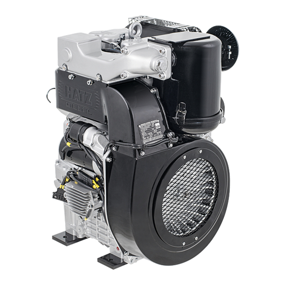
1.3. Type plate data If required In special cases only, e.g. engines acc. to Federal Authority for Automobilism. - Page 13 1.2. Engine illustration 1 Fuel line 18 Lubricating oil line (Feed pump - fuel injection pump) 19 Exhaust manifold 2 Air deflector 20 Fuel injection pump 3 Oil dipstick 21 Stop lever 4 Fuel return line 22 Speed control lever 5 Injector 23 Fuel feed pump 6 Lifting eye-bolt...
-
Page 14: Additional Equipment
2. Additional equipment... -
Page 15: Fuel Supply System
2.1. Fuel supply system 2.1.2. Fuel filter 2.1.1. Fuel tank Preparations: - Preparations: - Dismantling: Dismantling: - Disconnect the fuel supply line „1“ with - Disconnect the fuel-supply line „1“ with clamping device - 2 - and pull it off the clamping device - 2 - and pull it off the fuel filter. - Page 16 2.1.1. 2.1.2. 10 11 3 4 12 3 4 7 2...
-
Page 17: Fuel Feed Pump
2.1.3. Fuel feed pump Preparations: - Dismantling: - Disconnect the fuel supply line „32” with clamping device - 2 -and pull it off the fuel feed pump. - Remove parts # ,.33“ ... „40“.. Inspection / repair: This is only required if irregularities which could be attributable to the feed pump have been noted when operating the en- gine (poor suction/pumping action owing... - Page 18 2.1.3. 33 34 35 34 32 38 34 34 33...
-
Page 19: Fuel Solenoid
2.1.4. Fuel solenoid (2-4 ways solenoid) Function: With fuel solenoid in operation (with elec- tric voltage - see Chapt.10 -) the fuel flows in the sequence 1 → 2 → 3 → 4 through the solenoid. With shut-off volt- age „Stop” the direction of flow is 4 → 3 →... - Page 20 2.1.4. 039 514 00 039 557 00 PFR 2K 60A 493 PFR 2K 60A 511 490 214 00 039 557 10 PFR 2K 60A 493 PFR 2K 60A 515...
-
Page 21: Airfilter System
2.2. Airfilter system 2.2.1. Oilbath-airfilter – Preparations: – Dismantling: - Remove parts # „1“ ... „4“. Inspection / repair: - Visual inspection, especially for plane contact surface. - Maintenance work as per instruction book. Assembly: - Follow the reverse # procedure when assembling. - Page 22 2.2. 2.2.1. min-1 = 3600 < 12... = 82 < < 13... 10... = 82 = 91 min-1 = 3600...
-
Page 23: Dry-Type Airfilter
2.2.3. Maintenance indicator, 2.2.2. Dry-type airfilter mechanical (for dry-type (not mounted directly airfilters only) onto engine!) – – Preparations: - Preparations: - Dismantling: Dismantling: - Unscrew the maintenance indicator „8”. - Release the hose clips „1”. - Remove parts # „2” ... „6”. Inspection / repair: - Visual inspection. - Page 24 2.2. 2.2.2 2.2.3. 2.2.4.. 3 4 5...
-
Page 25: Maintenance Indicator, Electrical
2.2.4. Maintenance indicator, electrical (applicable for dry-type airfilters only) – Preparations: - Dismantling: - Disconnect the cable connection from the electrical system. Note the circuit diagram or wiring diagram! Chapt. 10. - Unscrew the maintenance switch „10”. Inspection / repair: - Visual inspection. - Page 26 2.2. 2.2.2 2.2.3. 2.2.4.. 3 4 5...
-
Page 27: Exhaust System
2.3. Exhaust system 2.3.1. Exhaust silencer and exhaust pipes – Preparations: - Dismantling: - Remove the parts dependent upon ver- sion and as required. Inspection / repair: - Visual inspection. Assembly: - Follow the reverse procedure when assembling. Note: If a new package of gaskets is installed, absolute attention must be paid to the two creased sheet metal radiators „A”... - Page 28 2.3. 2.3.1. Cylinder head Exhaust Exhaust Exhaust manifold...
-
Page 29: Electrical Equipment
2.4. Electrical equipment 2.4.1. Starter 2.4.2. Alternator – Attention: Magnetic ring „5” and coil „9” are identical Preparations: - for the 12 V- and 24 V - version; only a special regulator switch is inserted Dismantling: (Chapt. 2.4.3.) - Disconnect the battery. Note the order - / + ! –... - Page 30 2.4. 2.4.1. 2.4.2. 2.4.3. 2.4.4. 2.4.5. 14 5 12 2 1 11 6 7 8...
-
Page 31: Voltage Regulator
2.4.3. Voltage regulator 2.4.4. Glow plug (Alternator) – Attention: the voltage regulator is availa- ble in different designs: Preparations: - Difference: Dismantling: a) Cable connection - Disconnect the cable connection from b) Switch point of charging indicator lamp the electrical system. (See Chapt. - Page 32 2.4. 2.4.1. 2.4.2. 2.4.3. 2.4.4. 2.4.5. 14 5 12 2 1 11 6 7 8...
- Page 33 2.4.5. Gearring – Preparations: Chapt. 3.5.2. Dismantling: - Detach the gearring „14” from the flywheel by heating it specifically. If a new gearring is to be used, the old gearring can also be drilled open and chiselled off. Inspection / repair: - Visual inspection Check the tooth profile (engagement) and, if necessary, file down as required...
- Page 34 2.4. 2.4.1. 2.4.2. 2.4.3. 2.4.4. 2.4.5. 14 5 12 2 1 11 6 7 8...
-
Page 35: Engine-Monitoring System
2.5. Engine monitoring system (Sensors and control components) 2.5.1. Temperature switch 2.5.2. Oil pressure switch – – Preparations: Chapt. 3.2.1. Preparations: - Dismantling: Dismantling: - Disconnect the cable connection from - Disconnect the cable connection from the electrical system. the electrical system. Note the circuit diagram or wiring Note the circuit diagram or wiring diagram ! Chapt. - Page 36 2.5. 2.5.1. 2.5.2.
-
Page 37: Power-Take-Off Mechanical
2.6. Power-take-off mechanical 2.6.1. Stubshaft 2.6.2. Flexible coupling -33- - 24 - 25 - Preparations: – Preparations: - Dismantling: Dismantling: - Slacken the Allen screw „1” and unscrew - Remove the retaining screw „3” and it by two turns. washer „4” . - Screw in and tighten the forcing - Fit the puller - 24 - 25 - and pretension it screw - 33 - until noticeable pressure is... - Page 38 2.6. 2.6.1. 2.6.2. 2.6.3. 2.6.4. 25 24...
-
Page 39: Centrifugal Clutch
2.6.3. Centrifugal clutch 2.6.4. Power-take-off flange -33- -24- Preparations: - Preparations: – Dismantling: Dismantling: - Slacken the Allen screw „6“ and unscrew - Remove the retaining screw „8” and it by two turns. washer „9” . - Screw in and tighten the forcing - Fit the puller - 24 - and pretension it by screw - 33 - until noticeable pressure is screwing in the forcing screw. - Page 40 2.6. 2.6.1. 2.6.2. 2.6.3. 2.6.4. 25 24...
-
Page 41: Power-Take-Off, Hydraulic
2.7. Power-take-off, hydraulic 2.7.1. Mounting parts for hydraulic Note: pump - Due to technical improvements a modi- fied case is used since end of February – 1987 which is sealed by a plain com- pression ring towards the crankcase. Preparations: No adjustment of tooth backlash is Remove any additional equipment necessary. - Page 42 2.7. 2.7.1. 4 8 7 6 5 2 G 30 > 11... = 82 11 10 4 8 7 6 5 2 G 30 > 12... = 82 > 10... = 91 2 G 40 11 10...
-
Page 44: Basic Engine
3. Basic engine... - Page 46 3.0. Cross-reference list for dismantling...
-
Page 47: Fuel Pressure Pipes
3.1.1. Fuel pressure pipes 3.1.2. Injector -29 - Preparations: Chapt. 3.0. Preparations: Chapt. 3.0. Dismantling: Dismantling: - Unscrew the fuel pressure pipes, compl. - Disconnect the fuel lines „4” . # „1” ... „3”, and, if necessary, separate - Remove parts # „5” ... „8” . them by undoing the pipe clip „3”. - Page 48 3.1. 3.1.1. 3.1.2. 3.1.3. 3.1.4. 4 13 11 12 15 17 18 20 16 19 22 23 24 98.5 ±0.8...
-
Page 49: Injection Pump
3.1.3. Injection pump Assembly: - Follow the reverse # procedure when assembling. The shims „30” between injection pump Preparations: Chapt. 3.0. and crankcase adjust the start of delivery Dismantling: of the injection pump. Therefore refit gas- - Remove the fuel lines # „14” ... „20”. kets with the previous overall thickness. - Page 50 3.1. 3.1.1. 3.1.2. 3.1.3. 3.1.4. 4 13 11 12 15 17 18 20 16 19 22 23 24 98.5 ±0.8...
-
Page 51: Cooling Air Duct
3.2.1. Cooling air duct 3.2.3. Lub.oil line Preparations: Chapt. 3.0. Preparations: Chapt. 3.0. Dismantling: Dismantling: - Remove parts # „1" ... „14" Note the model version - Remove the parts, dependent upon version „19" ... „29” . Inspection/ Repair: - Visual inspection. Inspection / repair: - Visual inspection. - Page 52 3.2. 3.2.1. 3.2.2. 36/2 37/2 3.2.3. 36/1 37/1 3.2.4. 3.2.5. 31/3 34 33 31/2 31/1 < 11... 17/1 = 82 > 12... 17/2 = 82 14/1 14/2 14/3 10 9...
-
Page 53: Crankcase Breather
3.2.4. Crankcase breather 3.2.5. Air-intake manifold Preparations: Chapt. 3.0. Preparations: Chapt. 3.0. Dismantling: Dismantling: Note the model version ! Note the model version (flat - 36 - or up- - Remove parts # „30" ... „31” wards - 37 -) - Dismantle the breather valve „31"... - Page 54 3.2. 3.2.1. 3.2.2. 36/2 37/2 3.2.3. 36/1 37/1 3.2.4. 3.2.5. 31/3 34 33 31/2 31/1 < 11... 17/1 = 82 > 12... 17/2 = 82 14/1 14/2 14/3 10 9...
-
Page 55: Cylinder Head Cover
3.3.1. Cylinder head cover Assembly: - Measure bumping clearance and pay attention to different values (depending on engine version). See Chapt. 3.4.2. and 5.1. Preparations: - - Bond the gasket „10” into the cylinder Dismantling: head „9” with a little grease. - Remove parts # „1”... - Page 56 3.3. 3.3.1. 3.3.2. 3.3.3. 60 Nm 55 Nm...
-
Page 57: Pushrod And Pushrod Tubes
! For technical improvements at crankcase these baffles are deleted from series (2G30 ≥ 15 ..., 2G40 ≥ 11 ...). Chapt. 1.4. - The pushrods can be interchanged. Before fitting the relevant cylinder head, set the pushrods to bottom position by turning the camshaft. - Page 58 3.3. 3.3.1. 3.3.2. 3.3.3. 60 Nm 55 Nm...
-
Page 59: Cylinder
3.4.1. Cylinder 3.4.2. Piston Preparations: Chapt. 3.0 Preparations: Chapt. 3.0. Dismantling: - Slacken screw „1“ on the trim plate „4” - Remove the circlips „11”. and remove parts # „1“... „5” completely - Push out the piston pin „12" by hand from the top. - Page 60 3.4. 3.4.1. 3.4.2. 9 10 13 12 11 1 2 3 Piston variants and their bumping clearance data Ø (Bumping clearance) Utilization Ø Ident-Nr. 88.0 012 236 01 generelly, expect compressor 40.2 13.6 88.5 012 355 01 0.70 - 0.75 89.0 012 273 01 88.0...
-
Page 61: Crankcase Cover
3.4.3. Crankcase cover 3.4.4. Oil sump Preparations: Preparations: - Remove engine mounts # „14" ... „16“ - Remove the engine mount # „22"... „25“. Dismantling: - Remove parts # „17“ ... „21“. Dismantling: - Remove parts # „26” ... „32”. The suction pipe „33”... - Page 62 3.4. 3.4.3. 3.4.4.
-
Page 63: Conrod
3.4.5. Conrod -15-16- Preparations: Chapt. 3.0. Dismantling: - Unscrew the conrod bolts and remove the conrod „35" separately from the top and bottom. The big end bearing „36” can remain in the conrod. - Loosely bolt the conrod together. Note the #. Do not interchange the parts ! Inspection / repair: - Visual inspection. - Page 64 3.4. 3.4.5. < < < 15... 10... 16... 11... = 82 = 91 = 82 = 91 ~3.0 ~1.25...
-
Page 65: Oil Pump
3.5.1. Oil pump 3.5.2. Flywheel -18-19-24- Preparations: Chapt. 3.0. Preparations: Chapt. 3.0. Dismantling: Dismantling: - Remove parts # „1” ... „6“. - Remove parts „7” ... „9” . - Remove the flywheel „10” with puller - 24 -. Inspection / repair: If an additional equipment is attached, - Visual inspection. - Page 66 3.5. 3.5.1. 3.5.2. 6 5 4 3 2 1 7 8 9...
-
Page 67: Timing Cover
3.5.3. Timing cover Assembly: Timing cover - Adjust the axial play of crankshaft and - 28 - 29 - camshaft. The axial play is set by fitting one or Preparations: Chapt. 3.0. more gaskets „19” and is 0,10 - 0,30 mm Dismantling: for crankshaft and camshaft. - Page 68 3.5. 3.5.3. 18/1 11/1 11/2...
- Page 69 Assembly: Measured distance Number of Intermediate gear for hydraulic pump Protrution of gaskets „19“ - Follow the reverse # procedure when gearwheels assembling. 0,00 . . . 0,10 - Insert the shim(s) „25" in the crankcase. 0,11 . . . 0,30 Note the fitting dimension ! Chapt.
- Page 70 3.5. 3.5.3. 18/1 11/1 11/2...
-
Page 71: Crankshaft
3.6.1. Crankshaft - Position the crankcase top half assem- bly, preassembled, with bearing side Note: pointing upwards,Chapt. 4.7.3. Upon introduction of the 2 G 40 the - Set the markings • • · on the gearwheel crankshaft and big end have been modi- for the camshaft approximately to the fied (see also Chapt. - Page 72 3.6. 3.6.1. < < < 15... 10... 16... 11... = 82 = 91 = 82 = 91 ~3.0 ~1.25...
- Page 73 3.6.2. Governor lever and governor 3.6.3. Camshaft and governor spring Preparations: Chapt. 3.0. Preparations: Chapt. 3.0. IMPORTANT ! Dismantling: The camshaft must be removed and fitted - Remove the spring cotter „6” . as described below since, other-wise, the - Disengage and remove the governor bearing bores in the crankcase could be spring „7”...
- Page 74 3.6. 3.6.2. 3.6.3.
-
Page 75: Governor Lever
3.6.4. Crankcase Assembly: Governor lever Note the model version ! - Assemble the governor lever in accord- ance with the instructions Preparations: Chapt. 3.0. Chapt. 3.6.2. Dismantling: Model version ≤ 8210... - Chapt. 4.7. Note that the governor lever with bevel Inspection / repair: and injection quantity limiting screw be- - Visual inspection. - Page 76 3.6. 3.6.4. 3.6.5. 3.6.6. 3.6.7. 3.6.8. < 14... 10... SCHWARZ BLACK 20 22 24/1 < 15... 23/1 11... 23/2 23/3 18 19 21 9 10 < 10... < 11... 10...
-
Page 77: Speed Control, External Components
3.6.7. Speed control with integrated - Screw the extra fuel device „1" in until it extra fuel device only for projects 18.5 mm. with the eccentric ≥ 2G30-157 approximately at 11 o'clock position. ≥ 2G40-151 Note that the governor lever with flat and... - Page 78 3.6. 3.6.4. 3.6.5. 3.6.6. 3.6.7. 3.6.8. < 14... 10... SCHWARZ BLACK 20 22 24/1 < 15... 23/1 11... 23/2 23/3 18 19 21 9 10 < 10... < 11... 10...
-
Page 79: Stop Lever
Important Note ! 3.6.8. Stop lever This device is only mounted and appli- cable for engine specifications mentioned before. Dismantling: Performance adjustment which exactly - Dismantle cover # „18“ ... „24“ . conforms to the specification must be Inspection / repair: carried out on test benches only. - Page 80 3.6. 3.6.4. 3.6.5. 3.6.6. 3.6.7. 3.6.8. < 14... 10... SCHWARZ BLACK 20 22 24/1 < 15... 23/1 11... 23/2 23/3 18 19 21 9 10 < 10... < 11... 10...
- Page 81 3.7.1. Replacing oil seal ring (power-take-off side) - 27 - + 2 metal lamellas (thickness 0,05 mm) Preparations: Chapt. 2.6. Dismantling: - Push out the leaking oil seal ring. Inspection / repair: - Visual inspection. - Check that the oil-seal ring is correctly seated and check the crankshaft for scoring and running-in marks.
- Page 82 3.7. 3.7.1. (0.05mm) (0.05mm)
-
Page 84: Components-Repair Work
4. Components repair work... -
Page 85: Injection Equipment
4.1. Injection equipment 4.1.1. Injection valve IMPORTANT Keep your hands out of the nozzle jet. The jet of a spraying nozzle can cause - 34 - damage to your health. Dismantling: - Correct the injection pressure (if neces- - Dismantle the injection valve “1” # sary) by adjusting the spring tension „2“... - Page 86 4.1. 4.1.1.
-
Page 87: Cylinder Head
4.2. Cylinder head 4.2.1. Cylinder head Measurement procedure - Measure the valves and distance between surface and valve. - 9 - 10 - 11 - 12 - 13 - 14 - Measure the valve guides only when fitted ! Dismantling: If the valve guides „16”... - Page 88 4.2. 4.2.1. 15/4 13 15/3 15/1 15/2 15/5...
-
Page 89: Cylinders And Pistons
4.3. Cylinder and piston 4.3.1. Cylinder Repair: Operation 1. The honing brush must be moved axial- ly in the cylinder during rotation. Drilling machine approx. 80 - 100 r.p.m. 2. Recommended speed of rotation Honing lubricant consisting of lub.oil and approx. - Page 90 4.3. 4.3.1. 4.3.2.
-
Page 91: Piston
4.3.2. Piston Dismantling: Repair: - Remove the piston rings # „1" ... „3” from - Before any parts are re-used. they must the piston with the piston ring pliers - 4 -. be cleaned to remove oil carbon. Do not interchange the piston rings ! If a new set of piston rings is used, the cylinder must be rehoned! Chapt. - Page 92 4.3. 4.3.1. 4.3.2.
-
Page 93: Conrod
4.4. Conrod 4.4.1. Conrod b) Measure the small end bush „3“ only in fitted condition. If the bush is replaced, also measure - 15 - 16 - the bore of the con rod. Chapt. 7.5. Dismantling: - Remove the conrod bolts „1“ and sepa- c) Check the conrod with fitted bush „3“... - Page 94 4.4. 4.4.1.
-
Page 95: Crankshaft
4.5. Crankshaft 4.5.1. Crankshaft - 24 - 26 - 28 - Dismantling: Assembly: - Pull off the gearwheel „1“ with extractor - Fully insert the caps in the 7 mm bore - 24 - 26 - from the crankshaft „2". and lock by caulking. - Page 96 4.5. 4.5.1. 2/1 2/2 5 6 7...
-
Page 97: Camshaft And Governor
4.6. Camshaft and governor 4.6.1. Camshaft 4.6.2. Governor Dismantling: Dismantling: Camshaft assy. Gearwheel with governor - Remove the shim(s) „1“. - Remove parts # „7“ ... „9“. - Press the camshaft „6“ out of the gear- wheel „2“. Inspection: - Dismantle the camshaft # „3“ ... „6“. - Visual inspection Inspect the governor weights for wear in Inspection:... - Page 98 4.6. 4.6.1. 4.6.2.
-
Page 99: Crankcase
4.7. Crankcase 4.7.1. Crankcase bottom half 4.7.2. Crankcase top half - 1 - 21 - 22 - Dismantling: Dismantling: - Push out the bearing shells „2“ and - Push out the bearing shells „6“ and mark the previous installation position. mark the previous installation position. - Page 100 4.7. 4.7.1. 4.7.2.
-
Page 101: Alternator
4.8. Alternator 4.8.1. Alternator „Ducati” 14 V/18 A B. Resistance measurement - short circuit to ground - Test for short circuit to ground with a -35- multimeter - 35 -. Preparation: Dismantling: Set to Ω x 100 / scale Ω - Separate the stator „1“... - Page 102 4.8. 4.8.1. ≈ R ≈...
- Page 104 5. Settings...
-
Page 105: Bumping Clearance
5.1. Bumping clearance 5.1.1. Measuring the bumping clearance -7-8- Preparations: Chapt. 3.3.2. Bumping clearance – nominal value If the piston, cylinder, conrod, crankshaft (dimension „c”) and / or crankcase has been replaced, al- This value depends on - engine type and ways ensure that the correct bumping - design of piston clearance is observed. - Page 106 5.1. 5.1.1. Cyl. head gasket b = 0.6 / 0.7 0.8 / 0.9 0.9 / 1.0 1.1 / 1.2 mm c (Bumping clearance)
-
Page 107: Tappet Clearance
5.2. Tappet clearance 5.2.1. Setting tappet clearance Measurement procedure Preparations: Chapt. 3.3.1. - Measure the tappet clearance with a Setting method feeler gauge. Set only with engine cold (20 ± 10° C) . Note the setting dimension ! Cylinder 1 = flyhweel-side - clockwise Chapt. - Page 108 5.2. 5.2.1. 0.10mm...
-
Page 109: Start-Of-Injection Setting
5.3. Start of injection setting 5.3.1. Setting the start of delivery The start of delivery as well as injection 2. Instead of the pressure valve holder, quantity are basically pre-calibrated for all flywheel-side, connect the adapter „30” original injection pumps, delivered by with dial gauge „31”... - Page 110 5.3. 5.3.1. 0.10mm 0.20mm 0.30mm 10... 13... – 82 : 26° ±0.5 > 14... = 82 : 23° ±0.5 > 10... = 91 : 26° ±0.5...
- Page 111 This point is start of delivery of injection When the delivery begin is correctly ad- pump which must be compared with the justed and the injection pump is pre-cali- corresponding required value. brated according to our standard - see For this purpose different marks are avail- Chapt.
- Page 112 5.3. 5.3.1. 0.10mm 0.20mm 0.30mm 10... 13... – 82 : 26° ±0.5 > 14... = 82 : 23° ±0.5 > 10... = 91 : 26° ±0.5...
-
Page 113: Injected-Fuel Quantity Setting
5.4. Injected fuel quantity setting 5.4.1. Adjustment of delivery lift The adjustment procedure is as follows: Note: -15-30-31 - With the delivery lift (see Chapt. 1.3.) the output of the engine is defined and ad- justed. The following restrictions are ap- Preparation: plicable: Set the start of injection (delivery begin) - Page 114 5.4. 5.4.1.
- Page 115 Correction If fuel emerges even before the effective delivery lift setting, the injected fuel quan- tity is too low. If no fuel emerges at the effective delivery lift setting. the injected fuel quantity is too high. - Dependent upon version, adjust the quantity-limiting screw „16”...
- Page 116 5.4. 5.4.1.
-
Page 117: Engine Speed
5.5. Engine speed 5.5.1. Engine speed setting - mech. Setting the low-idle speed: -32- - On engines with blocked low-idle speed setting, the speed is set with the stop screw „5” to approx. 900 - 1000 r.p.m., Preparation: unless a speed other than this is re- - Remove the pipe clamp „1”... - Page 118 5.5. 5.5.1.
-
Page 119: Fuel Feed Pump
5.6. Fuel feed pump 5.6.1. Fuel feed pump - It is sufficient to carry out the idle-/resid- ual stroke test. A new adjustment becomes necessary if - either no resid- ual stroke - or too low an idle stroke Preparations: (<... - Page 120 5.6. 5.6.1. " " b " c " " a " "a" = 34.1 ± 0.1mm "c" = 1.8 – 2.1 mm 2 : Gesamthub (100%) 1 : Leerhub (50 - 80%) 2 : Resthub (20 - 50%)
-
Page 122: Function Tests
6.Function tests... -
Page 123: Injection Valve
6.1. Injection valve 6.1.1. Pressure and function tests -23- Preparations: Chapt. 3.1.2. Function test: Preparation - Connect the pressure pipe with testing device - 23 - to the pipe connection of the injection pump. - Remove the corresponding blank plug and connect the injection valve. - Page 124 6.1. 6.1.1.
-
Page 125: Pressure And Function Test
6.2. Injection pump 6.2.1. Pressure and function test -23- Preparation: Chapt. 3.1.1. Function test: Preparation - Loosen pressure pipes at injection pump and connect instead the testing device „23a” to the appertaining pressure pipe. - Set the speed control lever into „Start” position. - Page 126 6.2. 6.2.1. 400 bar...
-
Page 127: 4-Way-Fuel Solenoid
6.2.2. 4-way-fuel solenoid Preparations: - Pull off all hose connections from fuel solenoid. Test: - By turning the starter key in position „1” the valve solenoid gets current. The re- sult is the flow direction as shown in sketch „A” (can be tested by blowing through air). - Page 128 6.2. 6.2.2. Operation 1 - 2 - 3 - 4 STOP 4 - 2 - 3 - 1...
-
Page 129: Lub.oil Pressure
6.3. Lub.oil pressure 6.3.1. Pressure and function test Test conditions: -20- 1. correct viscosity class 2.Oil temperature: 100 ± 20 °C Preparations: Oil pressure Chapt. 3.2.3. Speed lower Function test: normal r.p.m. limit The lub.oil pressure is influenced by the 1,2 ... - Page 130 6.3. 6.3.1.
-
Page 131: Alternator And Voltage Regulator
6.4. Alternator-Voltage regulator 6.4.1. Function test - 35 - 36 - Preparations: - Chapt. 2.4.2. - Chapt. 2.4.3. Versions: There are two versions of this alternator, and they differ in respect of the design of the voltage regulator: - Previous version with plug connector on the voltage regulator housing. - Page 132 Type of fault Possible cause Test / remedy The charge indicator Lamp defective. Fit a new lamp. lamp does not light when the switch key Cable connection between igni- is in position I and tion switch (terminal 15) and with the engine terminal "L"...
- Page 133 Function tests Measuring the charging current - A voltage of at least 6 V must be meas- urable at terminal „0” or black cable*, using the multimeter - 35 - since the alternator cannot issue charging current otherwise. If the voltage is lower than this, check the cable connections for damage or charge the battery.
- Page 134 6.4. 6.4.1. Charging current curve for alternator 14V / 18A Ducati I (A) 1000 1500 2000 2500 3000 n (min ) Battery voltage max. 13 V black 58 50a 15 19 17 white P0123 yellow P,0,1 124 voltage regulator 126 alternator 129 charging indicator lamp 182 ignition switch A (mV)
- Page 135 Measuring the alternator no-load circuit Testing the impulse transmitter section in the voltage regulator This measurement permits the alternator section to be tested without voltage regu- The impulse transmitter section of the lator and battery. voltage regulator represents the ground - In order to conduct the measurement, connection of the charging indicator lamp switch off the engine and disconnect the...
- Page 136 6.4. 6.4.1. Idling voltage curve for alternator 14V / 18A Ducati U (V) 1000 1500 2000 2500 3000 Voltage measurement n (min ) (without battery and voltage regulator) between the two yellow cables (alternating current) Testing the impulse transmitter section in the voltage regulator black 58 50a 15 19 17...
- Page 137 6.4. 6.4.2. 2 G 30 - 157 [ f 2 G 30 / 2 G 40 2 G 30 - 151 [ c 2 G 40 - 151 [ c 2 G 30 - 172 34 36 28 34 36 26 34 36 92 34 36 31 34 36 26 - 8904...
- Page 138 7. Tables - wear ratings...
- Page 139 Tightening torques for threaded connections General requirements in Nm: Nm ÷ 9.81(10) = kpm Nm ÷ 1.3558 = lb ft Screw strength rating Thread 10.9 12.9 M 10 M 12 M 14 M 16 M 18 M 20 M 22 2G .
- Page 140 Tightening torques in Nm Cap nuts on fuel pressure pipe Hexagon nut - injection valve retention Nozzle retention - injection valve Hexagon nuts - injection pump retention Pipe connection of injection pump Hexagon nuts - rocker bracket retention Hexagon nuts - cylinder head retention 50/60* Hexagon nut - flywheel retention Hexagon screw for crankcase cover...
- Page 141 7.2. 7.2.1. c d e - 0.015 a = Ø 48.00 max. – - 0.035 + 0.065 b = Ø 45.00 max. 45.10 + 0.025 In bolted condition ! + 0.065 B = Ø 44.50 max. 44.60 + 0.025 + 0.018 c = Ø...
- Page 142 7.2. 7.2.2. < 11... = 82 a = Ø 16 h6 min. 15.90 - 0.011 + 0.003 b = Ø 16 min. 15.90 + 0.011 + 0.018 c = Ø 16 H7 max. 16.10 d = 9.00 e = 13.00 f = 21.00 + 0.081 >...
- Page 143 7.3. 7.3.1. M22 x 1.5 b f d2 c a2 f M18 x 1.5 + 0.015 + 0.015 a = Ø 38.485 a = Ø 45.00 min. 44.95 Standard + 0.005 + 0.015 Ø 44.50 min. 44.45 b = 58 x 38 x 0.2 / 0.3 -0.5 mm + 0.005 b = R 2.5...
- Page 144 7.4. 7.4.1. - 0.015 a = Ø 18.00 max. – - 0.026 + 0.10 b = Ø 18.00 max. 18.15 ( + 0.07 + 0.20 c = Ø 18.00 max. 18.30 ( + 0.10 d g e b + 0.003 ...
- Page 145 7.5. 7.5.1. 2 G 30 Ø 88.0 Ø 88.5 Ø 89.0 2 G 40 Ø 92.0 Ø 92.5 Ø 93.0 = 2.0 max. 2.30 = 2.0 max. 2.30 = 3.5 max. 3.65 + 0.007 a = Ø 26.00 max. 26.05 + 0.002 b = Ø...
- Page 146 7.6. 7.6.1. 2 G 30 + 0.01 Ø 88.0 max. 88.15 ( + 0.01 Ø 88.5 max. 88.65 ( + 0.01 Ø 89.0 max. 89.15 ( µ = 0.9 - 1.3 d = 0.5 2 G 40 ...
- Page 147 7.7. 7.7.1. + 0.016 a = Ø 15 f6 min. 14.90 ( + 0.027 + 0.018 b = Ø 15 H7 c* = R10 d = M8 x1 e = 0.2 / 0.3 0.1 - + 0.006 a = Ø 14 K7 max.
- Page 148 7.8. 7.8.1. a = 29.77 min. 29.70 ( – 0.025 – 0.060 b = 18.00 min. 17.89 ( – 0.080 c = 40.576 min. 40.45 ( – 0.025 d = 30.060 max. 30.10 ( – 0.030 Axial play: 0.01 - 0.05 mm New parts max.
- Page 150 8. Governor - injection system...
- Page 151 8.1. 8.1.1. KBEL 65 S 49 PFR 2K 60A PFR 2K Ø 1.8 mm DLLA 159S 1082 250 +8 bar > 10 ... = 82 > > 0.1 / 0.2 / 0.3 14 ... 10 ... 2 G 30 = 82 2 G 40 = 91 98.5 ±...
- Page 152 8.2. 8.2.1. applic. (min ) (mm) (mm) ≤ 3000 min 1500 Gen. 17.5 ≤ 2300 univers. 17.5 2300 17.0 univers. – 3000 17.5 17.0 3000 Gen. 17.5 8.3. 8.3.1. > 13 ... 26° ± 0.5 = 82 > 14 ... 23°...
- Page 154 9. Special tools / sealants and bonding agents...
- Page 155 Special tools and workshop equipments Engine type 2 G . . Ident-Nr. Code Designation 620 307 01 01.1.2 Strap wrench 668 383 00 01.1.2 Clamping device for fuel line 613 728 00 03.2.2 Flare nut wrench 17 - 19 mm 612 090 01 03.1.2 Piston ring pliers...
- Page 156 9.1. 9.1.1. 16/17 18 1D . . / 04.03...
- Page 157 Special tools and workshop equipments Engine type 2 G . . Ident-Nr. Code Designation 626 753 00 03.1.1 Impact hammer with fittings 665 030 01 05.1.1 Spill device for injection pump 612 087 00 05.1.2 Dial gauge - 1 / 100 mm 624 838 01 03.1.2 Rev.
- Page 158 9.1. 9.1.2.
- Page 159 Sealing and bonding agents Sealing and bonding agents are available from HATZ for use in maintenance and/or re- pair works. All items listed below may be ordered as individual spare parts. Refer to appropriate spare parts list for ordering. Application of sealing and bonding agents: The letter coding in the drawings indicates which agents should be applied when fitting the part refered to.
- Page 160 10. Wiring diagrams...
- Page 161 10. Wiring diagrams Note: The following wiring diagrams refer to electric equipment which has been sup- plied completely by HATZ. In many cases the machine manufacturer installs the electric equipment. In this case make use of the wiring dia- gram of the complete machine. 10.1.
- Page 162 10.1. Electric equipment with optical malfunction indicator Instruments box 151a P 0 1 2 3 P,0,1 151c 151b white black ϑ 161 162 yellow Engine Battery 121 Glow plug 158 Fuel shutt off solenoid Wiring to 172 by customer 10 123 Glow controller 159 Diode continuous duty solenoid...
- Page 163 10.2 Wiring diagram for the electric equipment with automatic shut-off device With this equipment malfunctions are indi- cated by the sensors "161" and "162" to the engine protection relay "177" which shuts off the engine via the solenoid "172" or the valve solenoid "158". With relay 177 the engine can also be stopped with the ignition key.
- Page 164 Electric equipment with automatic shut-off device 10.2. Instruments box 151a P 0 1 2 3 P,0,1 151b white black ϑ 161 162 176 yellow Engine 1) with solenoid only 2) with glow plug only Battery 121 Glow plug 159 Diode NOTE: 123 Glow controller 161 Temperature switch...
- Page 165 HYDRAULIC SYSYTEM...
- Page 166 LP8500 HYDRAULIC SYSTEM The Hydraulic system of the LP850 consists of a hydraulic tank, a triple gear pump, a valve block, four propulsion motors (two for left propulsion, and two for right propulsion 565 cc/rev=34.5 cu in/rev), one vibration motor, a hydraulic cooler, a hydraulic cooler by-pass valve (.55 Mpa=80 PSI), a return filter (by-pass at 0.17Mpa=25 PSI) and a hydraulic tank breather (.035Mpa=5 PSI).
- Page 179 Group 2 Gear Pumps and Motors Service Manual...
-
Page 180: Introduction
Gear Pumps and Motors Group 2 1. Introduction Using This Manual The purpose of this manual is to provide useful to change the rotation of the pump or motor. The information concerning assembling and disassem- appendix gives information on testing and relative bling of Group 2 pumps and motors. - Page 181 Gear Pumps and Motors Group 2 Contents 1. Introduction ..............................2 Using This Manual ..........................2 Safety Precautions ..........................2 Symbols Used in Sauer-Danfoss Literature ..................5 2. General Information ........................... 6 2.1 General Description ............................ 6 Design ..............................7 Model Code ............................
- Page 182 Gear Pumps and Motors Group 2 8. SKP2 Pumps ............................. 39 General Information ..........................39 8.1.2 Drive Gear Shaft Differences ....................... 40 8.1.3 Front and Rear Flange Differences ....................40 8.1.1 Bearing Block For SKP2 ......................40 8.1.4 Bearing Block Differences ......................41 Changing the Rotation of SKP2 ......................
-
Page 183: Symbols Used In Sauer-Danfoss Literature
Gear Pumps and Motors Group 2 Symbols Used in Sauer-Danfoss Literature Lubricate with hydraulic fluid. DANGER! May result in injury. Apply grease/petroleum jelly. May result in immediate or premature damage. Apply locking compound. Reusable part. Inspect for ware or damage. Nonreusable part, use a new part. -
Page 184: General Information
Gear Pumps and Motors Group 2 2. General Information 2.1 General Description Group 2 gear products consist of pumps, reversible Generally, all these products follow the same proce- pumps, uni- and bidirectional motors. This group of dures for assembling, disassembling, and servicing. gear pumps and motors is characterized by a wide In this manual, the SNP2 will be used as an example selection of components. -
Page 185: Design
Gear Pumps and Motors Group 2 Design Snap Ring Shaft Seal Outer Seal Bearing Block Assembly Drive Gear Body (Housing) Rear Cover Pressure Seal Front Flange Teflon Backup Ring Dowel Pin Idler Gear Capscrew P101 130... -
Page 186: Model Code
Gear Pumps and Motors Group 2 Model Code A B C D E Type SNP 2 Standard Gear Pump SKP 2 High Torque Gear Pump SHP 2 High Pressure Gear Pump SNI 2 Gear Pump with Internal Drain Relief Valve SNE 2 Gear Pump with External Drain Relief Valve Valve (omit when not used) - Page 187 Gear Pumps and Motors Group 2 A B C D E Variant Code (Three letter code describes valve settings or other variants to standard configuration) Variation on 09 flange to accommodate Perkins 900 series engine mounting Variant on standard straight shaft used with CI96 outrigger bearing option. Variant on standard tapered shaft used on CO91 outrigger bearing option.
-
Page 188: Technical Specifications
Gear Pumps and Motors Group 2 3. Technical Specifications 3.1 Hardware Specifications ] i s ] i s i n i i n i i n i ] i s ] i s i n i i n i i n i ] i s ] i s i n i... -
Page 189: System Specifications
Gear Pumps and Motors Group 2 System Specifications ° ° T101 001E T101 003E β β β β β n i l i n i β o i t β β ≥ 2 o i t t l i o i t β... -
Page 190: Servicing
Gear Pumps and Motors Group 2 4. Servicing Conversions Group 2 is a modular series. In particular, it is easy to make conversions on the pumps, e.g. changing rotation, replacing flange, drive shaft, seals, or assembling a tandem pump from two single pumps. On the following page are tables showing the allowable conversions. - Page 191 Gear Pumps and Motors Group 2 o l l o l l o l l - - - - - - s t l T101 135E The following conversion steps are allowed on the product groups listed below. i l u T101 136E...
-
Page 192: Disassembly
Gear Pumps and Motors Group 2 5. Disassembly General In the following pages a detailed procedure is given for disassembly and assembly of pumps and motors. Prior to proceeding it may be necessary to prepare some subassemblies separately. The details for preparing each subassembly are given in the following section. -
Page 193: Procedure
Gear Pumps and Motors Group 2 5.1.5 Procedure 1. Clamp the unit. Clamp the unit in a vice from the flange side. Make sure the vice jaws are clean and have smooth surfaces to prevent damage to the pump. Clamping the pump on the body is not recommended because serious damage to the surfaces, on which the ports are located, may occur. - Page 194 Gear Pumps and Motors Group 2 4. Remove front flange. Place the pump on the table and slowly remove the front flange. Be careful not to damage the shaft seal when removing the flange. Avoid contact of the shaft seal lips with keyway edges (in tapered and parallel shafts) or splined shaft teeth.
- Page 195 Gear Pumps and Motors Group 2 6. Remove bearing blocks and gears. Place the pump on its side and carefully remove the bearing block and gear set. To accomplish this, hold the pump body and push with your fingers on the rear bearing block. Mark the relative positions of the gear mesh (drive gear tooth to idler gear tooth) and the bearing blocks to the body so they can be reas-...
- Page 196 Gear Pumps and Motors Group 2 8. Remove Outer O-Ring Seal Check the quality of this seal. If necessary, replace it. Follow the same removal recommenda- tions given in step 7. After removal, discard the damaged seal. Important: Do not use tools with sharp edges to remove the seals, as damage to the cover can result.
-
Page 197: Assembly
Gear Pumps and Motors Group 2 6. Assembly 1. Prepare the seals. Have the entire seal kit available. Lightly coat all seals with seal grease. The grease is needed to adhere the seals to their grooves. Do not install dry seals. F101 011 2. - Page 198 Gear Pumps and Motors Group 2 4. Install pressure seals. • Pumps and Uni-Directional Motors Prepare the pressure seals by lightly lubri- cating them with grease. Install pressure seals into the grooves on the front flange and rear cover. Then install the teflon Teflon Backup Ring backup ring.
- Page 199 Gear Pumps and Motors Group 2 6. Install outer seal. Prepare the outer seal by lightly lubricating with grease. Install outer seals in the grooves on both sides of the body. F101 017 7. Prepare the gears. Caution: The gear surfaces are superfin- ished.
- Page 200 Gear Pumps and Motors Group 2 9. Assemble the bearing blocks and gears. Lubricate the journals and the gear faces. Assemble the bearing blocks and gears. Ensure that the recessed bearing faces are installed adjacent to the gear faces. Align all assembly marks made during disassembly.
- Page 201 Gear Pumps and Motors Group 2 12. Install the dowel pins. Install four 5 mm dowel pins into the proper cavities on both sides of the body (refer to the illustration). Swab the pins with assembly grease or petroleum jelly to retain them during assembly. Do not install dowel pins to the rear cover or flange, as one of them may drop inside the pump during assembly.
- Page 202 Gear Pumps and Motors Group 2 14. Install Rear Cover. Mount the cover on the body. Ensure the arrow on the back is oriented properly. The arrow should be: • In the same direction as the flow if the unit is Inlet For Inlet a pump.
- Page 203 Gear Pumps and Motors Group 2 17. Torque sequence. (all except 03 type) Note: When assembling units with 01 flange and short coupled tandems, wash the capscrews and apply Loctite ® 242 or equivalent thread lock compound to the threads before assembly. Install capscrews.
- Page 204 Gear Pumps and Motors Group 2 20. Prepare the unit for shipment or storage. Clean the exterior of the pump and install the following: • Port Plugs • Key (CI and CO shafts) • Shaft protective cap (CI and CO shafts) •...
-
Page 205: Multi Stage Pumps
Gear Pumps and Motors Group 2 7. Multi Stage Pumps General P101 133 7.1.1 Construction Multiple stage pumps may be purchased directly Socket head capscrews retain the front flange and from Sauer Danfoss, or individual stages can be rear cover of each stage. The assembly is held purchased and assembled. -
Page 206: First Stage Pump Preparation
Gear Pumps and Motors Group 2 First Stage Pump Preparation Front Drive Gear Rear Flange Flange (Shaft) Shaft Seal Shaft Seal Socket Head Capscrew* Socket Head Capscrew* Pressure Seals * Not used in converted first stage pumps. Idler Gear P101 134 7.2.1 General The figure above shows a cross section of a typical... -
Page 207: Converting A Single Stage Pump To A First Stage Pump
Gear Pumps and Motors Group 2 7.2.3 Converting a Single Stage Pump to a First Stage Pump To prepare a first stage unit from a single pump, A first stage pump when converted from a single following components are required: pump, will not require the small socket head capscrews as shown in the figure. -
Page 208: Intermediate Stage Pump Preparation
Gear Pumps and Motors Group 2 Intermediate Stage Pump Preparation Rear Shaft Seal Drive Gear Front Flange (Shaft) Coupling Socket Head Capscrew* Socket Head Capscrew* * Not used in converted Pressure Seals intermediate stage Rear Flange pumps. P101 135 7.3.1 General The figure above shows a cross section of a typical Intermediate stage pumps supplied from the fac-... -
Page 209: Converting A Single Stage Pump To An Intermediate Stage Pump
Gear Pumps and Motors Group 2 7.3.3 Converting a Single Stage Pump to an Intermediate Stage Pump To prepare an intermediate stage pump from a single stage pump, the following components are required: • SNP2/...FR03 type pump with the desired porting and rotation. -
Page 210: Final Stage Pump Preparation
Gear Pumps and Motors Group 2 Final Stage Pump Preparation Drive Gear Front Flange Rear Cover (Shaft) Coupling Socket Head Capscrew* Socket Head Capscrew* Pressure Seals * Not used on converted final stage pumps. P101 136 7.4.1 General The figure above shows a cross section of a typical Final stage pumps supplied from the factory are FR03 type pump. -
Page 211: Converting To A Rear Stage Pump
Gear Pumps and Motors Group 2 7.4.3 Converting to a Rear Stage Pump To prepare a final stage pump from a single stage pump, the following components are required: • SNP2 single stage pump with the desired porting and rotation. •... -
Page 212: Assembly Of Multi-Stage Pumps
Gear Pumps and Motors Group 2 Assembly of Multi-Stage Pumps 1. Install the coupling. Place the first stage pump on the work bench, so that the rear flange is in the upward position. If necessary, remove burrs on the flange. Blow the surface and cavity of the flange with compressed air to remove any debris before assembly. -
Page 213: Change Of Rotation
Gear Pumps and Motors Group 2 Change of Rotation 7.6.1 General 7.6.2 Determining the Direction of Rotation The SNP2 pumps are designed with the pressure The direction of rotation of a given flange can be seals located in grooves on the rear cover and front determined by referencing its part number in the flange. -
Page 214: Model Code
Gear Pumps and Motors Group 2 7.6.3 Model code 7.6.4 Conversion procedure Rotation is expressed in the model code as follows: To change rotation of a pump, the following compo- nents are required: SNP2/...x..• A front flange of the appropriate direction of Where ‘x’... - Page 215 Gear Pumps and Motors Group 2 2. Remove idler gear. Remove the idler gear from the body cavity, leaving the rear bearing block in place. F101 041 3. Move idler gear. Install the idler gear into the opposite position in the bearing block.
- Page 216 Gear Pumps and Motors Group 2 5. Install front bearing block. Install the front bearing block into the body cavity. Align the assembly marks. F101 043 6. Install the new front flange. Install the seals and assemble the new front flange Old Flange (CW) New Flange (CCW) onto the pump body.
-
Page 217: Skp2 Pumps
Gear Pumps and Motors Group 2 8. SKP2 Pumps General Information SKP2 Pumps are designed to accommodate an The differences between SKP2 and SNP2 pumps 11 tooth SAE splined shaft for higher torque are described in this section. applications. Front cover for clockwise and counter clockwise rotation Shaft Seal Snap Ring... -
Page 218: Drive Gear Shaft Differences
Gear Pumps and Motors Group 2 8.1.1 Bearing Block For SKP2 High Pressure Side In SKP2 pumps, the pressure seals are located on the bearing blocks as shown. Teflon Rubber Pressure Backup Ring Seal Low Pressure Side F101 046 8.1.2 Drive Gear Shaft Differences SNP2 Drive Gear The shaft on the drive gear for the SKP2 is larger than... -
Page 219: Bearing Block Differences
Gear Pumps and Motors Group 2 8.1.4 Bearing Block Differences SKP2 Bearing Blocks SNP2 Bearing Blocks In the SKP2, the pressure seal and backup ring are mounted in grooves on the bearing blocks, while in High Pressure the SNP2, the pressure seal and backup ring are mounted in grooves on the front flange and rear cover. -
Page 220: Changing The Rotation Of Skp2
Gear Pumps and Motors Group 2 Changing the Rotation of SKP2 There is no additional hardware required to change the rotation on an SKP2 pump. The instructions given here show the unique steps involved when converting pumps. In addition to these, follow the assembly and disassembly instruc- tions in sections 5 and 6. - Page 221 Gear Pumps and Motors Group 2 4. Install the drive gear / shaft. Reinstall the drive gear into the free side of the body cavity. Align the assembly marks on the gear teeth. F101 053 5. Install the front bearing block. Install the front bearing block into the body.
-
Page 222: Product Options
Gear Pumps and Motors Group 2 9. Product Options Rear Cover with Integral Priority Flow Divider Valve 9.1.1 General Information Group 2 pumps are offered with an optional priority flow divider valve integrated into the rear cover. Flow and pressure settings are made at the factory and are not adjustable. -
Page 223: Rear Cover With Integral Relief Valve
Gear Pumps and Motors Group 2 Rear Cover with Integral Relief Valve 9.2.1 General Information Group 2 pumps are offered with an optional adjust- able relief valve integrated into the rear cover. When necessary, the relief valve may be disas- sembled for cleaning and inspection. -
Page 224: Trouble Shooting
Gear Pumps and Motors Group 2 10. Trouble Shooting 10.1 Low or No Flow From Gear Pump Item Description Action 1. Check oil level in reservoir. Insufficient oil to supply gear pump. Fill reservoir to proper level. 2. Check input spline condition. Input shaft broken or stripped. - Page 225 Gear Pumps and Motors Group 2 Notes...
-
Page 226: Appendix
Gear Pumps and Motors Group 2 11. Appendix 11.1 Stud Specifications mm [in] Studs used to assemble multiple pumps must com- ply with the following specifications. ø 0.220 [0.009] • Type Stud • Thread Dimension ISO M10 • Design Standard DIN 931 [0.063] [0.063]... -
Page 227: Multi-Stage Pumps (General Rule)
Gear Pumps and Motors Group 2 11.2.2 Multi-Stage Pumps (General Rule) The following is a general rule that explains how to Given as a formula: calculate the stud length for any multiple combina- MSL = TBL + TRFL + TFFL + RCL + 14mm [0.55 in] tion of the SNP2 / SEP2 pump series. -
Page 228: Testing The Pumps And Motors
Gear Pumps and Motors Group 2 11.3 Testing the Pumps and Motors Test Relief Valve 11.3.1 General After assembling a pump, it should be tested to verify that volumetric efficiency is sufficient to insure satis- factory performance. Filter Outlet Pressure Prime Mover Motors can be tested as pumps. -
Page 229: Tables (Cont.)
Gear Pumps and Motors Group 2 11.3.3 Tables (cont.) T101 143E ] i s ] i s ] i s ] i s T101 144E ] i s ] i s ] i s ] i s T101 145E In addition to the prescribed test procedure, it is recommended that the 6cc motor be tested also as a motor. This can be done in the application by providing flow to the motor inlet to with no torque on the shaft at start-up. -
Page 230: Tools
Gear Pumps and Motors Group 2 11.4 Tools mm [in] This section contains drawings useful in fabricating any specialized tools required to service group 2 gear pumps and motors. 11.4.1 Shaft Seal Installation Tool 70 [2.756] 5 [0.197] 50 [1.969 ] [0.590 ] 3 [0.118] 12 [0.472]... -
Page 231: Shaft Seal Protective Sleeves
Gear Pumps and Motors Group 2 11.4.2 Shaft Seal Protective Sleeves mm [in] Ø17.7 +0.05 Ø17.7 +0.05 [0.697 +0.002 [0.697 +0.002 Ø17.4 Ø17.4 [0.685 ] [0.685 ] R0.1[.004] R0.1[.004] Ø13 Ø13 [0.512 ] [0.512 ] 10 ° 10 ° [0.118 ] Ø3 [0.118 ] Ø3... -
Page 232: Shaft Dimensions
Gear Pumps and Motors Group 2 mm [in] 11.5 Shaft Dimensions This section contains dimensions and specifications for standard shafts. 11.5.1 Shafts Used with 01 Flange CO01 Tapered Shaft Type: 1:8 Taper Shaft Key Data: 4 x 6.5 ISO 3912 Technical Specifications: Nut Torque: 35-50 Nm... - Page 233 Gear Pumps and Motors Group 2 mm [in] SC01 Splined Shaft Type: 9 Tooth Spline Spline Data: 17 x 14 DIN 5482 Circular Tooth Thickness (s 3.206 mm Profile Correction: + 0.6 Technical Specifications: Maximum Shaft Torque: 90 Nm [66 lbf•ft] P101 142E...
-
Page 234: Shafts Used With 02 Flange
Gear Pumps and Motors Group 2 mm [in] 11.5.2 Shafts Used with 02 Flange CO02 Taper Shaft Type: 1:5 Taper Shaft Key Data: 3 x 6.5 ISO 6604 (DIN 6888) Technical Specifications: Nut Torque: 40-50 Nm [30-37 lbf•ft] Maximum Shaft Torque: 140 Nm [103 lbf•ft] P101 143E... -
Page 235: Shafts Used With 04 / 05 Flange
Gear Pumps and Motors Group 2 mm [in] 11.5.3 Shafts Used with 04 / 05 Flange CO04 / CO05 Taper Shaft Type: 1:5 Taper Shaft Key Data: 3 x 6.5 ISO 6604 (DIN 6888) Technical Specifications: Nut Torque: 40-50 Nm [30-37 lbf•ft] Maximum Shaft Torque: 140 Nm... -
Page 236: Shafts Used With 06 Flange (Sae)
Gear Pumps and Motors Group 2 mm [in] 11.5.4 Shafts Used with 06 Flange (SAE) Cl06 Parallel Shaft Type: SAE A parallel Shaft Technical Specifications: Maximum Shaft Torque: 80 Nm [59 lbf•ft] P101 147E SC06 Splined Shaft Type: SAE 9 Tooth Spline Spine Data: 9T 16/32DP SAE J498b... - Page 237 Gear Pumps and Motors Group 2 mm [in] SKP2/...SC06 Splined Shaft Type: SAE 11 Tooth Spline Spine Data: 11T 16/32DP SAE J498b flat root side fit Circular Tooth Thickness: 0.127 mm [.005 in] less than standard SAE class 1 fit Technical Specifications: Maximum Shaft Torque: 150 Nm...
-
Page 238: Fr Tang Shaft
Gear Pumps and Motors Group 2 11.5.5 FR Tang Shaft mm [in] The shaft type shown in the drawing is called a “tang” shaft. This shaft is used in conjunction with an “Oldham” style coupling and is normally connected to another tang shaft on a P.T.O. (Power Take Off). This shaft is generally supplied with the 03/43 type flange, and is used as the front drive for multistage pumps. -
Page 239: Flange Types
Gear Pumps and Motors Group 2 11.6 Flange Types SNP 2/. . . CI 01 SNP 2/. . . SC 04 SEP 2/. . . CI 01 SNP 2/. . . CO 01 SNP 2/. . . CO 05 SEP 2/. . . CO 01 SHP 2/. - Page 240 Gear Pumps and Motors Group 2 Notes...
- Page 241 Gear Pumps and Motors Group 2 Notes...
- Page 242 Hydraulic Power Systems SAUER-Danfoss Hydraulic Power Systems - Market Leaders Worldwide SAUER-DANFOSS is a world leader in the design SAUER-DANFOSS specializes in integrating a full and manufacture of Hydraulic Power Systems. Research range of system components to provide vehicle designers and development resources in both North America and with the most advanced total-design system.
- Page 267 LP8500 ASSEMBLY and DISASSSEMBLY OF THE ECCENTRIC SHAFT 1-DISASSEMBLY 1.1-Remove the vibration motor (item 15), coupling (item 14) and pins (item 9). 1.2-Remove the end cover (item 3). 1.3-Remove the snap ring (item 5). 1.4-Place the housing (item 2) in a vertical position with the shaft end cover (item 11) to the top.
- Page 268 LP8500 Eccentric shaft 2.9-Slide the eccentric shaft (item 8) into the inner race of the bearing. 2.10-Install the shaft end cover (item 11) sliding the bearing onto the eccentric shaft journal. Apply Loctite 242 and torque the mounting screws (item 12) to 59 lb.ft (80 N.m).
- Page 277 ELECTRICAL SYSTEM...
- Page 278 File: d:\adobe\388377-RevB-Ver2.dwg...
- Page 279 File: d:\adobe\388377-RevB-Ver2.dwg...
- Page 280 File: d:\adobe\388377_1-RevB-Ver2.dwg...
- Page 281 File: d:\adobe\388377_1-RevB-Ver2.dwg...
- Page 282 LP8500 Electric Troubleshooting-3 Machine does not go into High Speed. 1-With the speed switch in High Speed, check if you have power to the high speed solenoid Y9 (X20) 1.1-Power 1.1.1-Replace solenoid Y9 1.2-No power 1.2.1-Move the harness plug to the Manual Operation Mode. 1.2.1.1-With high speed switch in High Speed check if you have power to solenoid Y9.
- Page 283 LP8500 Electric troubleshooting-1 1-Fuse #1 (30 A) blows when the emergency switch is turned on (Twist and pop). Move plug of wiring harness from remote to manual position. Pull relay K3 out of its socket. Check continuity between socket termi n a l s “ 8 7 ” a n d “ 8 5 ” . 1.1-If continuity is positive: 1.1.1-D i s c o n n e c t c o n n e c t o r “...
- Page 284 LP8500 Electric Troubleshooting-2 Engine does not start in remote control mode. Be sure that the transmitter battery is charged and that there is communication between the transmitter and receiver. 1-Move the wiring harness plug to the manual mode position. 1.2-Engine starts in Manual 1.3-Move harness plug back to the remote control mode position.
Need help?
Do you have a question about the 2G30 and is the answer not in the manual?
Questions and answers