
Related Manuals for Hatz Diesel 2-4L41C


Summary of Contents for Hatz Diesel 2-4L41C
- Page 1 CREATINGPOWER SOLUTIONS. 2-4L41C | 2-4M41 | 2-4M41Z | 4L42C | 4M42 OPERATOR’S MANUAL Diesel engine Hatz Diesel www.HATZ- DIESEL.com...
-
Page 3: Table Of Contents
2-4L41C, 2-4M41, 2-4M41Z, 4L42C, 4M42 Table of contents Table of contents Notices ......................General information ..................Safety ....................... General information ..................3.1.1 Intended use and foreseeable misuse .............. 3.1.2 Machine user or machine manufacturer obligations ......... 3.1.3 Representation of safety notes ................. - Page 4 Table of contents 2-4L41C, 2-4M41, 2-4M41Z, 4L42C, 4M42 Maintenance ....................55 General maintenance instructions ..............55 Maintenance work ..................... 56 8.2.1 Maintenance notice label .................. 56 8.2.2 Maintenance plan ....................58 8.2.3 Checking the intake area of the combustion air ..........60 8.2.4...
-
Page 5: Notices
2-4L41C, 2-4M41, 2-4M41Z, 4L42C, 4M42 Notices Notices Contact data © 2012 Motorenfabrik HATZ Ernst-Hatz-Straße 16 94099 Ruhstorf Germany Tel. +49 (0)8531 319-0 Fax +49 (0)8531 319-418 marketing@hatz-diesel.de www.hatz-diesel.com All rights reserved! Copyright The copyright for this Operator's Manual rests entirely with Motorenfabrik HATZ, Ruhstorf. -
Page 6: General Information
General information 2-4L41C, 2-4M41, 2-4M41Z, 4L42C, 4M42 General information Information on the document This Operator's Manual was created with due care. It is exclusively intended to offer a technical description of the machine and to provide instructions on commissioning, operating and maintaining the machine. When operating the machine, the applicable standards and legal regulations as well as any in- house regulations apply. -
Page 7: Safety
2-4L41C, 2-4M41, 2-4M41Z, 4L42C, 4M42 Safety Safety General information Introduction This chapter contains the information you need to work safely with this ma- chine. To prevent accidents and damage to the machine, it is imperative that these safety instructions be followed. -
Page 8: Machine User Or Machine Manufacturer Obligations
Machine manufacturer obligations If you have an engine that is not yet installed in a machine, it is imperative that you follow the Assembly Instructions for HATZ Diesel Engines be- fore installing the engine. These assembly instructions contain important in- formation on how to safely install the engine and are available at your near- est HATZ service station. -
Page 9: Representation Of Safety Notes
2-4L41C, 2-4M41, 2-4M41Z, 4L42C, 4M42 Safety Storing the Operator's Manual This Operator's Manual is an integral component of the machine (also when being sold). It must be stored in the direct vicinity of the machine and be ac- cessible to personnel at all times. -
Page 10: Meaning Of Safety Symbols
Safety 2-4L41C, 2-4M41, 2-4M41Z, 4L42C, 4M42 Danger symbol/ Meaning signal word This signal word, without a danger symbol, is CAUTION used to indicate the risk of property damage. This signal word indicates additional useful infor- NOTICE mation, such as operating tips and cross referen- ces. -
Page 11: Safety Notes
2-4L41C, 2-4M41, 2-4M41Z, 4L42C, 4M42 Safety Symbol Meaning Warning of heavy loads! Warning of environmental damage! Comply with the Operator's Manual or additional documenta- tion from other manufacturers or the user. Additional information that is useful to the reader. Safety notes 3.2.1 Operational safety... - Page 12 Safety 2-4L41C, 2-4M41, 2-4M41Z, 4L42C, 4M42 Using the machine ▪ Only operate the machine for the purposes described in the chapter 3.1.1 Intended use and foreseeable misuse, page 7. Compliance with other regulations ▪ Adhere to the applicable accident prevention regulations of the trade asso- ciations.
- Page 13 2-4L41C, 2-4M41, 2-4M41Z, 4L42C, 4M42 Safety Personal protective Pictogram Function equipment Safety goggles Safety goggles protect the eyes (with side protection) from flying objects (e.g. dust particles, spraying liquids, spraying acid). Working clothes Wear close-fitting clothing. How- ever, it must not restrict the wearer's freedom of movement.
-
Page 14: Machine-Specific Safety Instructions For Operation
If you have an engine that is not yet installed in a machine, it is imperative that you follow the Assembly Instructions for HATZ Diesel Engines be- fore installing the engine. These assembly instructions contain important information on safe installa- tion. - Page 15 2-4L41C, 2-4M41, 2-4M41Z, 4L42C, 4M42 Safety Safe operation ▪ Before switching on the machine, ensure that no one can be injured when the machine is started up. ▪ During machine operation, ensure that unauthorized persons do not have access to the area in which the machine has an impact.
-
Page 16: Machine-Specific Safety Instructions For Maintenance Work
Safety 2-4L41C, 2-4M41, 2-4M41Z, 4L42C, 4M42 CAUTION Danger of injury from defective crankhandle. A damaged or broken handle bar can cause injuries. A worn cranking shaft can slip out of the starting mechanism when start- ing and also cause injuries. - Page 17 2-4L41C, 2-4M41, 2-4M41Z, 4L42C, 4M42 Safety Safety instructions for maintenance work DANGER Danger of explosion from flammable cleaning agents. Cleaning with benzene is an explosion hazard. It is highly flam- mable, can become electrostatically charged and can generate an explosive gas-air mixture.
-
Page 18: Electrical Equipment
Safety 2-4L41C, 2-4M41, 2-4M41Z, 4L42C, 4M42 3.2.4 Electrical equipment Safety notes DANGER Danger to life, danger of injury or danger of property dam- age due to incorrect use of batteries. ▪ Do not place tools on the battery. ▪ Before performing work on the electrical equipment, always disconnect the negative terminal of the battery. -
Page 19: Labels
2-4L41C, 2-4M41, 2-4M41Z, 4L42C, 4M42 Safety NOTICE ▪ The necessary wiring diagrams are included with the ma- chine if it is equipped with electrical equipment. Additional wiring diagrams can be requested when needed. ▪ We cannot be held liable for electrical equipment that is not designed according to HATZ wiring diagrams. - Page 20 Safety 2-4L41C, 2-4M41, 2-4M41Z, 4L42C, 4M42 The engine type plate is located on the crankcase or sound protection hood and contains the following engine information: Number of the engine family or the EU approval (for engines with ex- haust certificate only) Engine type, customer specification and setting of pumping start (°...
- Page 21 2-4L41C, 2-4M41, 2-4M41Z, 4L42C, 4M42 Safety Label Meaning CAUTION! Damage from inadequate engine cooling. ▪ Only run the engine when all cov- ers are installed. 0000 036 144 Refuel with diesel fuel only. Specifi- cation, see the chapter 4.2 Fuel,...
-
Page 22: Technical Data
Technical data 2-4L41C, 2-4M41, 2-4M41Z, 4L42C, 4M42 Technical data Engine Type 2L41C 3L41C 4L41C / 4L42C 2M41. 3M41. 4M41. / 4M42 Type Air-cooled four stroke diesel engine Combustion system Direct injection Number of cylinders Bore/stroke 102 / 105 102 / 105... -
Page 23: Fuel
2-4L41C, 2-4M41, 2-4M41Z, 4L42C, 4M42 Technical data Engine oil capacities and dipstick equipment Type Oil sump Engine oil capacity Mark on the dip- stick liters 2L41C With 2M41Z Without 2M41 With Without 3L41C With 10.5 3M41Z Without 3M41 With 11.0... -
Page 24: Engine Oil
Technical data 2-4L41C, 2-4M41, 2-4M41Z, 4L42C, 4M42 Lowest ambient tempera- Percentage of petroleum [%] for ture at start [°C] Summer fuel Winter fuel ‑ 0 to -10 ‑ -10 to -15 -15 to -20 ‑ -20 to -30 Engine oil... -
Page 25: Engine Design
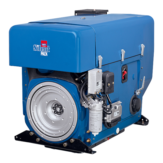
2-4L41C, 2-4M41, 2-4M41Z, 4L42C, 4M42 Engine design Engine design Engine 2-4L41C Encapsulated model "Silent Pack" Pos. Designation Access cap for fuel feed pump Oil filling opening and dipstick Type plate Speed control lever Oil filter Exhaust silencer (encapsulated) Cover for air guide housing (access to cooling fan belt) - Page 26 Engine design 2-4L41C, 2-4M41, 2-4M41Z, 4L42C, 4M42 Pos. Designation Retractable lifting eye, max. load 5000 N Capsule intake shaft Intake opening for combustion air Fuel feed line with fuel prefilter Fuel return line Cover plate on exhaust side Central connector for electrical equipment...
- Page 27 2-4L41C, 2-4M41, 2-4M41Z, 4L42C, 4M42 Engine design Pos. Designation Speed control lever Oil filter Exhaust silencer (encapsulated) Cover for air guide housing (access to cooling fan belt) Engine brackets Oil drain screw Cover plate on operating side Side wall Exhaust air duct Capsule hood Retractable lifting eye, max.
- Page 28 Engine design 2-4L41C, 2-4M41, 2-4M41Z, 4L42C, 4M42 Engine 2-4M41, 2-4M41Z Standard model Pos. Designation Oil filling opening and dipstick Side trim panel Intake opening for combustion air Cooling fan belt Cooling fan with installed three phase alternator 1/2-inch square socket for turning the engine...
- Page 29 2-4L41C, 2-4M41, 2-4M41Z, 4L42C, 4M42 Engine design Pos. Designation Fuel return line Fuel feed line with fuel prefilter Type plate Silencer Central connector for electrical equipment Battery connections Powerbox Electrical maintenance switch for air filter Engine 4M42 Standard model Pos.
- Page 30 Engine design 2-4L41C, 2-4M41, 2-4M41Z, 4L42C, 4M42 Pos. Designation 1/2-inch square socket for turning the engine Oil drain screw Speed control lever Oil filter Oil drain screw (on oil sump) Cooling air guide for oil cooler Fuel filter Cylinder head cover Air filter housing cover Lifting eye, max.
-
Page 31: Transport, Assembly And Commissioning
5 or www.hatz-diesel.com. Assembly instructions Assembly notes HATZ diesel engines are efficient, robust and long-lived. Therefore, they are usually installed in machines that are used for commercial purposes. The machine manufacturer must follow the applicable regulations regarding machine safety – the engine is a part of a machine. -
Page 32: Preparations For Commissioning
Transport, assembly and commissioning 2-4L41C, 2-4M41, 2-4M41Z, 4L42C, 4M42 Depending on the use and installation of the engine, it may be necessary for the machine manufacturer and machine user to install safety equipment to prevent inappropriate use. Note the following: ▪... -
Page 33: Operation And Use
2-4L41C, 2-4M41, 2-4M41Z, 4L42C, 4M42 Operation and use Operation and use Safety notes NOTICE Comply with the safety chapter! Follow the basic safety instructions in the chapter 3 Safety, page 7. WARNING Danger of injury from damage and defects on the machine. -
Page 34: Start Preparation
Operation and use 2-4L41C, 2-4M41, 2-4M41Z, 4L42C, 4M42 Procedure Step Test The machine is standing securely and on a level surface. The installation location is adequately ventilated. There is a sufficient amount of fuel in the fuel tank (see the chap- ter 4.2 Fuel, page 23). -
Page 35: Pumping Fuel With The Manual Fuel Pump
2-4L41C, 2-4M41, 2-4M41Z, 4L42C, 4M42 Operation and use Overview Pos. Designation Manual lever (fuel feed pump) Return line Procedure Step Activity Fill with fuel if necessary. Remove the access cap for the fuel feed pump. Actuate the manual lever (1) on the fuel feed pump until the fuel audibly flows back into the fuel tank through the return line (2). - Page 36 Operation and use 2-4L41C, 2-4M41, 2-4M41Z, 4L42C, 4M42 Model with manual fuel pump Only for 4L42C and 4M42 Pos. Designation Bleed screw Filter Rubber ball Procedure Step Activity If there is air in the fuel system: Fill with fuel if necessary.
-
Page 37: Setting The Speed Control
2-4L41C, 2-4M41, 2-4M41Z, 4L42C, 4M42 Operation and use Setting the speed control Overview ½ Procedure Step Activity Depending on the situation, place the speed control lev- er in either the "1/2" or "Start" position. NOTICE A lower speed setting will cause less exhaust smoke when start- ing. -
Page 38: Starting The Engine With Crankhandle
Operation and use 2-4L41C, 2-4M41, 2-4M41Z, 4L42C, 4M42 Safety notes DANGER Danger to life from inhaling exhaust gases. Toxic engine exhaust gases can lead to loss of consciousness and even death in closed-off and poorly ventilated rooms. ▪ Never operate the machine in closed-off or poorly ventilated rooms. - Page 39 2-4L41C, 2-4M41, 2-4M41Z, 4L42C, 4M42 Operation and use Turning over the engine: Safety note CAUTION Danger of engine damage from decompression while the engine is running. ▪ Do not operate the decompression lever while the engine is running. Overview Decompression lever...
- Page 40 Operation and use 2-4L41C, 2-4M41, 2-4M41Z, 4L42C, 4M42 Preparation Step Activity Carry out start preparations (see the chapter 7.3 Start prepara- tion, page 34). Move the speed control lever into position "Start" (see the chap- ter 7.4 Setting the speed control, page 37).
- Page 41 2-4L41C, 2-4M41, 2-4M41Z, 4L42C, 4M42 Operation and use Starting the engine Safety note CAUTION Danger of injury from recoiling of the engine. ▪ Use a crankhandle with a recoil damper. ▪ Hold the handle bar so that it cannot twist and quickly turn the crank so that continuous traction between the engine and crank is ensured.
- Page 42 Operation and use 2-4L41C, 2-4M41, 2-4M41Z, 4L42C, 4M42 Crankhandle Attach the crankhandle Pos. Designation Handle bar Crank arm Drive dog Guide sleeve Preparation The decompression lever must be set depending on the number of cylinders of the engines 2-4M41.. Operator's Manual...
- Page 43 2-4L41C, 2-4M41, 2-4M41Z, 4L42C, 4M42 Operation and use Step Activity Setting the decompression lever: ▪ Two cylinder engine 2M41. Turn the lever to position "2". ▪ Three cylinder engine 3M41. Turn the levers of the 1st and 3rd cylinders to position "2".
-
Page 44: Starting The Engine With An Electric Starter
Operation and use 2-4L41C, 2-4M41, 2-4M41Z, 4L42C, 4M42 Step Activity Turn the crankhandle forcefully with increasing speed. When the decompression lever engages in the "0" position (compression), the highest possible speed must be reached. As soon as the engine starts, pull the crankhandle out of the guide sleeve (4). - Page 45 2-4L41C, 2-4M41, 2-4M41Z, 4L42C, 4M42 Operation and use Procedure NOTICE ▪ Start for max. 30 seconds. If the engine is still not running after that, turn the starting key back to position "0" and elimi- nate the cause (see the chapter 9.1 Troubleshooting, page 93).
- Page 46 Operation and use 2-4L41C, 2-4M41, 2-4M41Z, 4L42C, 4M42 Step Activity As soon as the engine is running, release the starting key. ▪ The starting key springs back to position "I" and remains in this position during operation. ▪ The charge control (2) and oil pressure display (3) go out.
-
Page 47: Switching Off The Engine
2-4L41C, 2-4M41, 2-4M41Z, 4L42C, 4M42 Operation and use NOTICE If the electronics indicate a problem continuously for more than 15 minutes without interruption (flash code - display lamp (5)), the engine switches off automatically. ▪ If the problem persists, the engine can be started but only for another 15 minutes. -
Page 48: Switching Off The Engine (Mechanical)
Operation and use 2-4L41C, 2-4M41, 2-4M41Z, 4L42C, 4M42 CAUTION Danger of engine damage. ▪ Never stop the engine on the decompression lever. The engine can be switched off in different ways depending on how it is equipped: ▪ Speed control lever (mechanical) ▪... -
Page 49: Switching Off The Engine (Electrical)
2-4L41C, 2-4M41, 2-4M41Z, 4L42C, 4M42 Operation and use 7.6.2 Switching off the engine (electrical) Overview Pos. Designation Operation Procedure NOTICE Danger of full battery discharge. ▪ When the machine is switched off, always turn the starting key to position "0" or else the battery may become fully dis- charged. -
Page 50: Refueling
Operation and use 2-4L41C, 2-4M41, 2-4M41Z, 4L42C, 4M42 NOTICE If the engine stops again immediately after starting, or stops in- dependently during operation, this is an indication that a moni- toring element of the automatic shutoff has been activated. Procedure... -
Page 51: Checking The Water Separator
2-4L41C, 2-4M41, 2-4M41Z, 4L42C, 4M42 Operation and use CAUTION Danger of environmental damage from spilled fuel. Do not overfill the fuel tank and do not spill fuel. ▪ Collect emerging fuel and dispose of it in an environmentally compatible manner. - Page 52 Operation and use 2-4L41C, 2-4M41, 2-4M41Z, 4L42C, 4M42 Pos. Designation Drain plug Bleed screw Procedure Step Activity Place a suitable container under the drain plug (1). NOTE: In inaccessible locations, an extension hose can be mounted on the drain screw (1).
-
Page 53: Checking The Oil Level And Adding Oil If Necessary
2-4L41C, 2-4M41, 2-4M41Z, 4L42C, 4M42 Operation and use Checking the oil level and adding oil if necessary Safety notes CAUTION Danger of burns. There is a danger of burns when working on a hot engine. ▪ Wear safety gloves. CAUTION Danger of later engine damage. - Page 54 Operation and use 2-4L41C, 2-4M41, 2-4M41Z, 4L42C, 4M42 Procedure — Checking oil level/adding oil Step Activity Switch off the engine and wait several minutes for the engine oil to collect in the crank housing. The machine must be horizontal. Remove contamination on the engine in the area of the dipstick (1).
-
Page 55: Maintenance
2-4L41C, 2-4M41, 2-4M41Z, 4L42C, 4M42 Maintenance Maintenance General maintenance instructions Safety notes WARNING Danger of injury from the failure to follow the operating in- structions and from performing unauthorized tasks on the machine. ▪ Follow all instructions. ▪ Do not perform activities for which no qualification is availa- ble. -
Page 56: Maintenance Work
Maintenance 2-4L41C, 2-4M41, 2-4M41Z, 4L42C, 4M42 ▪ Before starting, ensure that no persons are located in the danger zone of the engine or machine. Performance of maintenance work The entire machine is designed to be maintenance friendly. Parts that re- quire maintenance are easily accessible. - Page 57 2-4L41C, 2-4M41, 2-4M41Z, 4L42C, 4M42 Maintenance 2M41. Without oil sump 0,1 mm 0.004" 2M31 2M40 2M41 = 1h 250h 500h 2M41. With oil sump; 3-4M41. and 4M42 in general 0,1 mm 0.004" .M31/.M40 .M41/.M42 = 1h 500h 250h H A T Z...
-
Page 58: Maintenance Plan
Maintenance 2-4L41C, 2-4M41, 2-4M41Z, 4L42C, 4M42 2-4L41C; 4L42C 8.2.2 Maintenance plan The degree of contamination of the fuel, the care with which refueling is per- formed and the soiling on the inside of the fuel tank are decisive in determin- ing the change interval of the fuel prefilter and the fuel filter. - Page 59 2-4L41C, 2-4M41, 2-4M41Z, 4L42C, 4M42 Maintenance Symbol Maintenance in- Maintenance activity/check Chapter terval Every 250 operat- Change the engine oil (2M41. 8.2.5 Change the 250h ing hours without oil sump, 2-4L41C engine oil, and 4L42C in general). page 64 Clean the cooling fan, cooling 8.2.6 Cleaning...
-
Page 60: Checking The Intake Area Of The Combustion Air
Maintenance 2-4L41C, 2-4M41, 2-4M41Z, 4L42C, 4M42 Symbol Maintenance in- Maintenance activity/check Chapter terval Change the engine oil (2M41. 8.2.5 Change the with oil sump, 3-4M41. and engine oil, 4M42 in general). page 64 Changing the oil filter. 8.2.13 Changing the oil filter,... - Page 61 2-4L41C, 2-4M41, 2-4M41Z, 4L42C, 4M42 Maintenance Overview 2-4M41 and 4M42 2-4L41C and 4L42C Pos. Designation Intake opening for combustion air Dust outlet opening Cyclone (option) Procedure Step Activity Check the intake opening (1) for coarse contamination such as leaves, heavy dust deposits, etc., and clean if necessary.
- Page 62 Maintenance 2-4L41C, 2-4M41, 2-4M41Z, 4L42C, 4M42 Electrical air filter maintenance display 2-4L41C and 2-4M41 4L42C and 4M42 Pos. Designation Air filter maintenance display Mechanical air filter maintenance display Pos. Designation Red field Procedure Step Activity For the electrical air filter maintenance display:...
-
Page 63: Checking The Cooling Air Area
2-4L41C, 2-4M41, 2-4M41Z, 4L42C, 4M42 Maintenance Step Activity Briefly let the engine run at maximum speed and watch for the indicator (5) to light up for a short period – depending on the version. In the engines 4L42C and 4M42, the following flash code indi- cates that maintenance work is required on the air filter ▪... -
Page 64: Change The Engine Oil
Maintenance 2-4L41C, 2-4M41, 2-4M41Z, 4L42C, 4M42 CAUTION Danger of engine damage from overheating. The engine temperature display (option) lights up as soon as the engine becomes impermissibly hot. ▪ Switch off the engine immediately and eliminate the cause. NOTICE In case of heavy contamination, shorten the maintenance inter- vals accordingly (see the chapter 8.2.2 Maintenance plan,... - Page 65 Unscrew the oil drain screw (1) and drain the oil entirely. When unscrewing the oil drain screw (1) on engines of type 2-4L41C and 4L42C, ensure that the drain pipe (2) is not loos- ened. Hold it with an open-end wrench.
-
Page 66: Cleaning The Cooling Fan, Cooling Fins And Oil Cooler
Maintenance 2-4L41C, 2-4M41, 2-4M41Z, 4L42C, 4M42 Pos. Designation Dipstick Mark on the dipstick Adding oil Step Activity Add engine oil to the max. mark on the dipstick (1). ▪ For the specification and viscosity, see the chapter 4.3 En- gine oil, page 24. - Page 67 2-4L41C, 2-4M41, 2-4M41Z, 4L42C, 4M42 Maintenance CAUTION Danger of injury. When working with compressed air, foreign bodies may fly into your eyes. ▪ Wear safety goggles. ▪ Never direct the compressed air jet toward people or toward yourself. CAUTION Danger of engine damage from overheating.
- Page 68 Maintenance 2-4L41C, 2-4M41, 2-4M41Z, 4L42C, 4M42 Overview — Preparatory activities Pos. Designation Baffle plate Preparation Step Activity Unscrew the following on encapsulated engines: ▪ Hood ▪ Side wall with speed control lever ▪ Cover plate on operating side ▪ Exhaust air duct ▪...
- Page 69 2-4L41C, 2-4M41, 2-4M41Z, 4L42C, 4M42 Maintenance Overview — Cleaning Procedure — Cleaning Step Activity Cleaning in case of dry dirt contamination Clean the cooling fan, cylinder head and cylinder with a suita- ble brush. Blow out the entire cooling air area with compressed air.
-
Page 70: Checking The Screw Connections
Maintenance 2-4L41C, 2-4M41, 2-4M41Z, 4L42C, 4M42 Step Activity Determine the cause of the oil contamination and have leaks corrected by the HATZ service station. Mount the capsule and air guide parts again. Let the engine run warm to prevent rust formation. - Page 71 2-4L41C, 2-4M41, 2-4M41Z, 4L42C, 4M42 Maintenance CAUTION Danger of injury There is a danger of injury when performing cleaning work at the exhaust screen. ▪ Wear safety gloves. NOTICE Operation of the engine for a lengthy period without a load or with only a small load can result in premature deposits on the screen insert.
-
Page 72: Changing The Fuel Prefilter
Maintenance 2-4L41C, 2-4M41, 2-4M41Z, 4L42C, 4M42 8.2.9 Changing the fuel prefilter Safety notes DANGER Fire hazard from fuel. Leaked or spilled fuel can ignite on hot engine parts and cause serious burn injuries. ▪ Never refuel in the vicinity of open flames or sparks that can cause ignition. - Page 73 2-4L41C, 2-4M41, 2-4M41Z, 4L42C, 4M42 Maintenance Overview Pos. Designation Fuel lines Fuel prefilter Procedure Step Activity Place a suitable container under the filter to collect emerging fuel. Close the fuel feed line. Pull the fuel lines (1) off of the fuel prefilter (2) on both sides.
-
Page 74: Maintaining The Dry Air Filter
Maintenance 2-4L41C, 2-4M41, 2-4M41Z, 4L42C, 4M42 Step Activity After completion, insert the access cover to the fuel feed pump back in the side wall. 4L42C and 4M42 If you have difficulties starting the engine, bleed the injection system with the aid of the manual fuel pump (see the chapter 7.3.2 Pumping fuel with the manual fuel pump, page 35). - Page 75 2-4L41C, 2-4M41, 2-4M41Z, 4L42C, 4M42 Maintenance Pos. Designation Clamp Removing the air filter cartridge - engines 2-4L41C and 4L42C Step Activity Remove the capsule hood. Remove adherent dirt in the area of the air filter housing (4). Only loosen the screws (1) to the point where you can lift off the complete air filter housing (4).
-
Page 76: Checking And Cleaning The Air Filter Cartridge
Maintenance 2-4L41C, 2-4M41, 2-4M41Z, 4L42C, 4M42 Pos. Designation Filter cover Spacer Bushing Filter cartridge Air filter housing Removing the air filter cartridge - engines 2-4M41. and 4M42 Step Activity Release the clamps (1) and remove the cover of the air filter housing (2). - Page 77 2-4L41C, 2-4M41, 2-4M41Z, 4L42C, 4M42 Maintenance NOTICE ▪ The pressure must not exceed 5 bar. ▪ A distance of approx. 150 mm must be maintained between the filter cartridge and the compressed air gun. ▪ Even minor damage in the areas of the sealing surface, filter paper or filter cartridge makes it impossible to reuse the fil- ter cartridge.
-
Page 78: Check And Set The Tappet Clearance
Maintenance 2-4L41C, 2-4M41, 2-4M41Z, 4L42C, 4M42 Mechanical air filter maintenance display Pos. Designation Red field Reset button Mounting the air filter cartridge Step Activity When assembling, mount the parts individually one after the oth- er to make sure they are correctly seated and to ensure leak tightness. - Page 79 2-4L41C, 2-4M41, 2-4M41Z, 4L42C, 4M42 Maintenance Overview — Preparatory activities Pos. Designation Square opening Hex nut Cylinder head cover Preparation — Adjusting the tappet clearance Step Activity On encapsulated engines, remove the hood of the capsule (see the chapter 5 Engine design, page 25).
- Page 80 Maintenance 2-4L41C, 2-4M41, 2-4M41Z, 4L42C, 4M42 Numbering of the valves and cylinders from the fan side Setting method for two cylinder engine Step Activity Set the valve of the 1st cylinder – fan side – to overlap (outlet valve not yet closed, intake valve begins to open).
- Page 81 2-4L41C, 2-4M41, 2-4M41Z, 4L42C, 4M42 Maintenance Overview — Adjusting the tappet clearance Pos. Designation Hex nut Adjusting screw Feeler gauge Procedure — Adjusting the tappet clearance Step Activity Check the tappet clearance with the feeler gauge (3). For the setting, see the chapter 4 Technical data, page 22.
-
Page 82: Changing The Oil Filter
Maintenance 2-4L41C, 2-4M41, 2-4M41Z, 4L42C, 4M42 Step Activity After a brief trial run, check the cylinder head cover for tight- ness. 8.2.13 Changing the oil filter Safety notes CAUTION Danger of burns. When working on the engine there is a danger of burns from hot oil. -
Page 83: Change The Fuel Filter
2-4L41C, 2-4M41, 2-4M41Z, 4L42C, 4M42 Maintenance Step Activity Add engine oil to the max. mark on the dipstick. ▪ For the specifications and viscosity, see the chapter 4.3 En- gine oil, page 24. ▪ The mark on the dipstick indicates whether the engine is equipped with an oil sump or not (see the chapter 4.1 En-... - Page 84 Maintenance 2-4L41C, 2-4M41, 2-4M41Z, 4L42C, 4M42 CAUTION Danger of environmental damage from spilled fuel. When the filter is removed, a small amount of fuel is drained as well. ▪ Collect emerging fuel and dispose of it in an environmentally compatible manner.
- Page 85 2-4L41C, 2-4M41, 2-4M41Z, 4L42C, 4M42 Maintenance Step Activity Slide on the strap wrench (1) and unscrew the fuel filter counter- clockwise. Dispose of the old filter in accordance with local environmental regulations. Lightly oil the gasket of the new fuel filter.
- Page 86 Maintenance 2-4L41C, 2-4M41, 2-4M41Z, 4L42C, 4M42 Step Activity Release the drain screw (1) and drain the fuel. Overview 4L42C and 4M42 Pos. Designation Strap wrench (HATZ order no.: 620 307 01) Gasket Procedure 4L42 C and 4M42 Step Activity Slide on the strap wrench (1) and unscrew the fuel filter counter- clockwise.
-
Page 87: Checking That The Air Filter Maintenance Indicator Is Working Properly
2-4L41C, 2-4M41, 2-4M41Z, 4L42C, 4M42 Maintenance 8.2.15 Checking that the air filter maintenance indicator is working properly Overview Electrical Mechanical air filter maintenance display air filter maintenance display Hose of air intake pipe Pos. Designation Red field Reset button Hose... - Page 88 Maintenance 2-4L41C, 2-4M41, 2-4M41Z, 4L42C, 4M42 Procedure Step Activity Remove the capsule hood and the side panel trim (see the chapter 5 Engine design, page 25). Turn the starting key to position I. Pull the hose (3) off of the exhaust manifold.
-
Page 89: Renewing The Poly V Belt And Checking The Function Of The Switch-Off Unit
2-4L41C, 2-4M41, 2-4M41Z, 4L42C, 4M42 Maintenance 8.2.16 Renewing the poly v belt and checking the function of the switch- off unit NOTICE When changing the belt: ▪ Always check the function of the switch-off unit. The switch- off pin must emerge by spring force, or else the machine will not switch off automatically if the belt tears. - Page 90 Maintenance 2-4L41C, 2-4M41, 2-4M41Z, 4L42C, 4M42 Pos. Designation Pulley Procedure — Removing the poly v belt Step Activity Unscrew one cylinder screw (1) from the pulley (3). Push back the tension pulley (2) and lock it using the cylinder screw (1).
- Page 91 2-4L41C, 2-4M41, 2-4M41Z, 4L42C, 4M42 Maintenance Procedure — Checking the function of the switch-off unit of the belt monitor- ing system Step Activity Release the piston with the tension pulley (1) by removing the cylinder screw. ▪ The piston with the tension pulley is pushed out of the housing by spring pressure.
- Page 92 Maintenance 2-4L41C, 2-4M41, 2-4M41Z, 4L42C, 4M42 Overview — Centering the pulley Pos. Designation Cylinder screw Procedure — Centering the pulley Step Activity Lightly secure the pulley with a cylinder screw (1) without plac- ing the pulley fully on the centering.
-
Page 93: Faults
2-4L41C, 2-4M41, 2-4M41Z, 4L42C, 4M42 Faults Faults Troubleshooting Troubleshooting notes If the cases listed below have been worked through but the fault continues to persist, please contact your nearest HATZ service station. Type of fault Possible causes Remedy Chapter The engine does... - Page 94 Faults 2-4L41C, 2-4M41, 2-4M41Z, 4L42C, 4M42 Type of fault Possible causes Remedy Chapter After every extended period of disuse, if 6.2 Assem- you experience difficulties starting the bly instruc- engine that can be eliminated by activat- tions, ing the feed pump for a lengthy period,...
- Page 95 2-4L41C, 2-4M41, 2-4M41Z, 4L42C, 4M42 Faults Type of fault Possible causes Remedy Chapter Starter speed is too Change the engine 4.3 Engine low: oil and add oil of oil, page 24 the right viscosity ▪ Oil is too vis- 8.2.5 class.
- Page 96 Faults 2-4L41C, 2-4M41, 2-4M41Z, 4L42C, 4M42 Type of fault Possible causes Remedy Chapter Fuel prefilter is Change the fuel 8.2.9 clogged. prefilter. Changing the fuel pre- filter, page 72 Fuel filter is clog- Change the fuel fil- 8.2.14 ged. ter.
- Page 97 2-4L41C, 2-4M41, 2-4M41Z, 4L42C, 4M42 Faults Type of fault Possible causes Remedy Chapter Torn cooling fan Renew the poly v 8.2.16 Re- belt. belt. newing the poly v belt and check- ing the func- tion of the switch-off unit, page 89 Mechanical faults.
- Page 98 Faults 2-4L41C, 2-4M41, 2-4M41Z, 4L42C, 4M42 Type of fault Possible causes Remedy Chapter The engine loses The fuel supply is Add fuel. 7.7 Refuel- power and speed. impaired ing, page 50 Change the filter. ▪ The tank ran out 8.2.9...
-
Page 99: Emergency Start
2-4L41C, 2-4M41, 2-4M41Z, 4L42C, 4M42 Faults Type of fault Possible causes Remedy Chapter Inadequate cool- Clean the cooling 8.2.6 Clean- ing: air area. ing the cool- ing fan, ▪ Contamination in cooling fins the entire area of and oil cool-... - Page 100 Faults 2-4L41C, 2-4M41, 2-4M41Z, 4L42C, 4M42 CAUTION Danger of later engine damage. The monitoring components (oil pressure, charge control and engine temperature) are deactivated in emergency operation. ▪ The oil level must be checked before the emergency opera- tion phase.
- Page 101 2-4L41C, 2-4M41, 2-4M41Z, 4L42C, 4M42 Faults Step Activity Place a suitable tool, such as a screwdriver, behind the emer- gency start lever (2) and tear the seal wire (3) between the emergency start lever and the housing screw with a forceful jerk.
-
Page 102: Storage And Disposal
Storage and disposal 2-4L41C, 2-4M41, 2-4M41Z, 4L42C, 4M42 Storage and disposal 10.1 Storing the machine General information NOTICE Comply with the safety chapter! Follow the basic safety instructions in the chapter 3 Safety, page 7. Storing the machine for a lengthy period... -
Page 103: Installation Declaration
2-4L41C, 2-4M41, 2-4M41Z, 4L42C, 4M42 Installation declaration Installation declaration Exte n d e d De c la ra tio n o f In c o rp o ra tio n EC Ma c h in e ry Dire c tive 2006/42/EC The ma nufa cture r: Mo to re n fa b rik Ha tz Gm b H &... - Page 104 CALIFORNIA Proposition 65 Warning Diesel engine exhaust and some of its constituents are known to the State of California to cause cancer, birth defects, and other reproductive harm.
- Page 105 Motorenfabrik Hatz GmbH & Co. KG Ernst- Hatz- Str. 16 94099 Ruhstorf a.d. Rott Deutschland Tel. +49 8531 319- 0 Fax +49 8531 319- 418 marketing@hatz- diesel.de www.hatz- diesel.com 0000 433 402 10 - 11.2014 - 3 Printed in G ermany CREATINGPOWER SOLUTIONS.
- Page 106 Technical Library http://engine.od.ua...
Need help?
Do you have a question about the 2-4L41C and is the answer not in the manual?
Questions and answers