Table of Contents
Advertisement
I I N N C C L L U U D D E E S S S S U U P P P P L L E E M M E E N N T T A A L L I I N N F F O O R R M M A A T T I I O O N N T T O O
T T H H E E O O W W N N E E R R ' ' S S M M A A N N U U A A L L F F O O R R M M O O D D E E L L Y Y E E A A R R 2 2 0 0 1 1 5 5
E E P P A A C C E E R R T T I I F F I I E E D D N N O O N N R R O O A A D D C C O O M M P P R R E E S S S S I I O O N N - -
I I G G N N I I T T I I O O N N E E N N G G I I N N E E S S . .
I I N N C C L L U U D D E E S S S S U U P P P P L L E E M M E E N N T T A A L L I I N N F F O O R R M M A A T T I I O O N N F F O O R R
T T H H E E U U S S E E O O F F E E P P A A C C E E R R T T I I F F I I E E D D E E N N G G I I N N E E S S W W I I T T H H I I N N
C C A A L L I I F F O O R R N N I I A A . .
CREATING POWER SOLUTIONS.
2G40 | 2G40 H
Translation of the
ORIGINAL
INSTRUCTION BOOK
Hatz Diesel
www.HATZ-DIESEL.com
Advertisement
Table of Contents

Related Manuals for Hatz Diesel 2G40 H


Summary of Contents for Hatz Diesel 2G40 H
- Page 1 CREATING POWER SOLUTIONS. 2G40 | 2G40 H I I N N C C L L U U D D E E S S S S U U P P P P L L E E M M E E N N T T A A L L I I N N F F O O R R M M A A T T I I O O N N T T O O T T H H E E O O W W N N E E R R ’...
- Page 2 A new HATZ Diesel engine - working for you This engine is intended only for the purpose determined and tested by the manufacturer of the equipment in which it is installed. Using it in any other manner contravenes the intended purpose.
-
Page 3: Table Of Contents
Contents Page Page Important notes on safe operation 5.3. Maintenance every 250 of the engine hours of operation 5.3.1. Maintenance work on oilbath Description of the engine air cleaner 5.3.2. Engine oil change an General information oil filter renewal 3.1. Technical data 5.3.3. -
Page 4: Important Notes On Safe Operation Of The Engine
Important notes on safe operation of the engine HATZ diesel engines are economical, stronly built and long-lasting. They are therefore frequently chosen for commercially and industrially operated equipment and machinery. Since the engine forms part of the finished equipment or machine, its manufacturer will take all the applicable safety regulations into account. - Page 5 Important notes on safe operation of the engine – Stop the engine before performing any maintenance, cleaning- or repair work. – Stop the engine before refuelling. Never add fuel near a naked flame or a source of sparks. Don't smoke. Don't spill fuel. –...
-
Page 6: Description Of The Engine
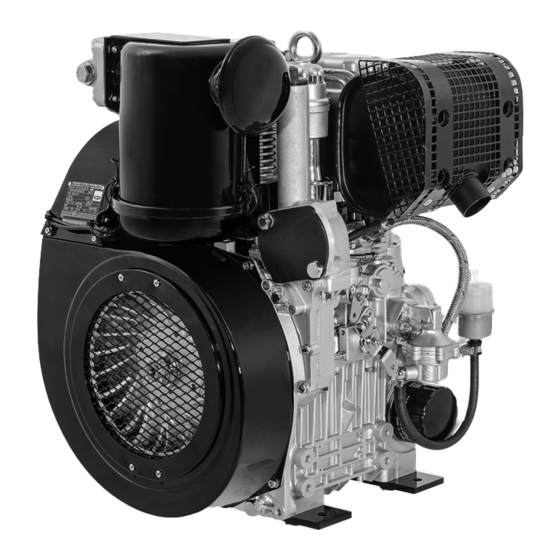
Description of the engine Fig. 1 1 Fuel line (feed pump – 12 Oilbath air cleaner 25 Oil drain plug fuel-injection pump) 13 Oil pressure switch 26 Guard 2 Air deflector 14 Rainproof cap 27 Air guide housing 3 Oil dipstick 15 Oil filler cap 28 Separable connector 4 Fuel return line... -
Page 7: General Information
General remarks 3.1. Technical data Type 2G40 / 2G40 H Design Air-cooled four-stroke diesel engine Combustion system Direct injection Number of cylinders Bore/stroke 92 / 75 Displacement cm³ Engine oil content 2.5 excl. sump incl. filter renewal l. approx. 3.0 incl. sump Difference between „max“... -
Page 8: Transport
3.2. Transport The lifting eyebolt provided as stand- The permitted loads and elements on ard equipment is intended for safe the speed adjusting lever and the stop movement of the engine. lever should be observed as an exess can lead It is not intended for lifting complete machin- to damage to the contacts and inner governor ery to which the engine is attached, and this is... -
Page 9: Epa / Carb - Type Plate
3.5. EPA/CARB-type plate and Every engine is equipped with an additional loose engine type plate. If the original type fuel label plate on the engine is not readily visible after The layout of the EPA / CARB - type plate depends the engine is installed in the equipment then on the engine application and is placed on the the second loose type plate must be attached... -
Page 10: Operation
When adding oil or checking the level, the en- Operation gine must be in a horizontal position. 4.1. Before initial start-up Engines are normally delivered without fuel and oil. 4.1.1. Engine oil Oil quality Qualified are all trademark oils which fulfil at least one of the following specifications: ACEA –... -
Page 11: Oilbath Air Cleaner
4.1.2. Oilbath air cleaner 4.1.3. Fuel If a cyclone-type dust trap is fitted, make sure Stop the engine before refuelling. that the dust outlet is pointing in the correct Never add fuel near a naked flame or direction. a source of sparks. Don't smoke. Use only pure fuel and clean filling equipment. -
Page 12: Starting The Engine
4.2. Starting the engine Do not run the engine in closed or badly ventilated rooms – danger of poisoning! Before starting the engine, make sure that no one is within the danger area near the engine or the machinery it is driving, and that all the necessary guards are installed. -
Page 13: Electric Starter
– As soon as the engine runs, release the start key. It must return to position I by itself and remain in this position during operation. The battery charge telltale and oil pressure warning must go out immediately after start- ing. -
Page 14: Engine Use
Preheating device with automatic heating 4.3. Engine use timer (additional equipment) Engines certified for constant or variable speed The preheating light „6“ lights up additionally at within a certain operating range, must be operat- temperatures below 0° Celsius (Fig. 12). ed according to the operator’s manual of the ma- chine. -
Page 15: Stopping The Engine
4.4. Stopping the engine Stop Start Start Stop – The battery charge telltale light „2“ and the oil pressure warning light „3“ come on. – Move speed control lever „1“ back to the – Turn the starter key back to position „0“ and „STOP“... -
Page 16: Maintenance
Maintenance The engine must be stopped before any maintenace work is attempted. Comply with legal requirements when handling and disposing of old oil, filters and cleaning materials. Keep the engine's starting key and starting handle out of reach of unauthorized persons. To immobilize engines with an electric starter, disconnect the negative battery terminal. - Page 17 0,1 mm 0.004" 2G40 250h 500h = 1h 0000 040 096 02 The above maintenance chart is supplied with For new or reconditioned engines, the following every engine. This label should be affixed to the must always be carried out after the first 25 engine or equipment in an easily visible position.
-
Page 18: Maintenance Every
8 – 15 With oilbath air cleaner: 5.2. Maintenance work every operating hours 5.2.1. Check engine oil level When the oil level is checked, the engine must be stopped and in a horizontal position. – Remove any dirt in the dipstick area. –... -
Page 19: Check The Cooling Air System
– Check that connecting hose „3“ and hose clips 5.2.3. Check the cooling air system „4“ are in good condition and not leaking Heavy contamination is an indication that in- (fig. 17). creased dust accumulation necessitates acorre- spondingly shorter maintenance interval. –... -
Page 20: Maintenance Every
5.3. Maintenance work every operating hours 5.3.1. Maintenance work on oilbath air cleaner – Detach upper part of air cleaner „1“ from engine and rinse in diesel fuel. – Allow the diesel fuel drip off thoroughly, or wipe it off, before re-assembling. –... - Page 21 – Slacken off and unscrew the throwaway engine oil filter using HATZ strap wrench „1“, Order No. 620 307 01, or a similar tool. – Take out drain plug „1“ and allow the oil to drain out completely (fig. 22 without oil sump, fig.
-
Page 22: Check And Adjust Vlave Clearances
– After cleaning, press the mesh screen back on 5.3.3. Check and adjust vlave clearances to the oil pressure relief valve. – Adjust only when the engine is cold (10 - 30 °C). – Remove any dirt from the area where the cover is attached to the cylinder head. -
Page 23: Clean The Cooling Air System
Adjusting: If dirt deposits are damp or oily: – Disconnect the battery. – Measure valve clearance with 0.10 mm feeler gauge „5“ (fig. 27, chapt. 3.1.). – Apply a detergent solution (cold cleaner or similar) to the entire system in accordance –... -
Page 24: Check Threaded Connections
5.3.5. Check threaded connections 5.4. Maintenance work every hours of operation Check the condition and tightness of all threaded connections, pipes and lines, hose clips and 5.4.1. Renew the fuel filter other fastenings on the engine or its mountings The maintenance intervals for the fuel filter are which can be reached during maintenance work. -
Page 25: Dry-Type Air Cleaner Maintenance
5.4.2. Dry-type air cleaner maintenance Cleaning the filter cartridge Dry contamination It is best to clean the filter cartridge only when the maintenance indicator displays the appropri- ate signal. This is only the case if the mainte- nance indicator functions properly (chap. 6.1.). Apart from this, the cartridge should be renewed after 500 hours of operation. -
Page 26: Functional Test
– Create a vacuum at the maintenance switch Functional test with powerful suction, indicator lamp „1“ must light up (fig. 33). 6.1. Air filter maintenance indicators (only on version with Dry-type – If there is no reaction, check cable connectors air cleaner) and replace filament lamp and/or maintenance switch if necessary. -
Page 27: Malfunctions - Causes - Remedies
Malfunctions – causes and remedies Malfunctions Possible causes Remedy Chap. The engine does Speed adjustment lever in the not start or not im- stop or idle position. Move the lever in START mediately, can Stop lever in stop position. position. 4.2.1. - Page 28 Malfunctions Possible causes Remedy Chap. At low Starting speed too low: temperatures. - Oil too viscous. Replace and fill up with oil. 5.3.2. 4.1.1. - Battery inadequately charged. Check the battery, if necessary contact a service station. Starter motor does Descrepancies in the electrical not operate or en- system:...
- Page 29 Malfunctions Possible causes Remedy Chap. Engine shuts down Fuel supply interrupted: independently dur- - Tank run dry Fill up with fuel. 4.1.3. ing operation. - Fuel filter blocked. Replace fuel filter. 5.4.1. - Fuel feed pump defective. Check the entire fuel supply system.
- Page 30 Malfunctions Possible causes Remedy Chap. Drop off in engine Air filter contaminated. Clean air filter. 5.3.1. performance and 5.4.2. speed, black Incorrect valve clearances. Adjust valve clearances. 5.3.3. smoke from the exhaust. Injector jets unserviceable. See workshop manual. Engine runs very Too much oil in the engine.
-
Page 31: Work On The Electrical System
– When carrying out welding work on the en- Work on the electrical gine or attached equipment, attach the earth system (ground) clip as near as possible to the weld- ing point, and disconnect the battery. If an al- Batteries generate explosive gases. ternator is fitted, separate the plug connector Keep them away from naked flame and leading to the voltage regulator. -
Page 34: Supplemental Information To The Owner's Manual For Model Year 2015 Epa Certified Nonroad Compression Ignition Engines
SUPPLEMENTAL INFORMATION TO THE OWNER'S MANUAL FOR MODEL YEAR 2015 EPA CERTIFIED NONROAD COMPRESSION IGNITION ENGINES. EPA EMISSION CONTROL SUPPLEMENTAL WARRANTY STATEMENT AND EMISSION-RELATED INSTALLATION INSTRUCTIONS. - Page 35 MAINTENANCE AND WARRANTY. SUPPLEMENTAL INFORMATION TO THE OWNERS MANUAL FOR MODEL YEAR 2015 EPA CERTIFIED NONROAD COMPRESSION IGNITION ENGINES. The following supplemental information is furnished for EPA Nonroad Compression Ignition Engines which are certified according to 40 CFR Part 89 and Part 1039. This information contains the following specific items: •...
- Page 36 • Exhaust manifold • Oil filler cap • Intake and exhaust gaskets at head interfaces • Emission Control Information Labels Only parts manufactured by Hatz and which have passed the Hatz Quality Assurance Program are assured of meeting EPA exhaust emission regulations. UNUSUAL OPERATING CONDITIONS.
- Page 37 Therefore, the maintenance work has to be carried out by a qualified workshop. Hatz authorised workshops, for example, are qualified workshops. Hatz Diesel of America will give you respective addresses, if required. EMISSION CONTROL SYSTEM AND ADJUSTMENTS. The emission control system for this engine is DI (Direct Injection) and EM (Engine Modification).
- Page 38 EPA EMISSION CONTROL WARRANTY STATEMENT YOUR WARRANTY RIGHTS AND OBLIGATIONS. Motorenfabrik Hatz GmbH & Co. KG warrants the emission control system on your engine for the periods of time listed below provided there has been no abuse, neglect or improper maintenance of your engine. Your emission control system includes: •...
- Page 39 30 days. If you have any questions regarding your warranty rights and responsibilities, you should contact HATZ DIESEL OF AMERICA, Inc. at (262) 544-0254. HATZ DIESEL SUPPLEMENTAL WARRANTY FOR MODEL YEAR 2015 EPA...
- Page 40 PARTS WITH SUPPLEMENTAL LIMITED WARRANTY. The following limited warranty is supplemental to the standard HATZ DIESEL LIMITED ENGINE WARRANTY and covers Model Year 2015 EPA certified engines and applies to the following exhaust emission-related components: • Fuel injection pump • Injection nozzle(s) •...
- Page 41 SUPPLEMENTAL LIMITED WARRANTY. Hatz Diesel of America, Inc. hereinafter referred to as “HATZ” warrants each of the above-listed parts when installed in a new engine sold by Hatz to be free from defects in material and workmanship under normal use and service, only under the named warranty...
- Page 42 EMISSION-RELATED INSTALLATION INSTRUCTIONS “Failing to follow these instructions when installing a certified engine in a piece of nonroad equipment violates federal law (40CFR1068.105(b)), subject to fines or other penalties as described in the Clean Air Act.” “If you install the engine in a way that makes the engine's emission control information labels hard to read during normal engine maintenance, you must place duplicate labels on the equipment.”...
- Page 43 INSTRUCTIONS ON THE INSTALLATION OF THE EXHAUST SYSTEM Following are the instructions to properly install the exhaust system and related components consistent with the EPA emission regulation requirements. 2 G 40 Exhaust-silencers and protection guard The exhaust silencer is fitted in connection with spring washers. Fixation is done by Allen screws.
- Page 44 Dismantling: • Remove in numerical sequence 1...4. Assembly: • Assemble in reverse sequence. • Apply lubricant as specified by HATZ. • Ensure gasket-kit is fitted in correct sequence i.e. the creased gaskets 4 face towards exhaust silencer. • Use anti-seize compound J as specified by HATZ.
- Page 45 SAMPLING OF EXHAUST EMISSIONS After the engine is installed in the equipment and placed in service, the sampling of exhaust emissions can be performed in a way that prevents diluting the exhaust sample with ambient air as follows: Version 1 Specification 1: Adding a 20-centimeter linear extension to the exhaust pipe...
- Page 46 Version 2 Specification 2: Adding a 20-centimeter bended extension to the exhaust pipe Version 1 Version 2 Clamp Engine type Ø d (mm) HATZ-Ident. Nr. HATZ-Ident. Nr. HATZ-Ident. Nr. 2 G 40 (H) 830 582 00 830 853 00 503 398 00...
-
Page 48: Supplemental Information To The Owner's Manual For The Use Of Epa Certified Engines Within California
SUPPLEMENTAL INFORMATION TO THE OWNER'S MANUAL FOR THE USE OF EPA CERTIFIED ENGINES WITHIN CALIFORNIA. - Page 49 The following information's are taken from the official CARB website and this page last reviewed October 31, 2012. For the latest information's please see http://www.arb.ca.gov/msprog/offroad/preempt.htm "The 1990 amendments to the federal Clean Air Act preempt California control of emissions from new farm and construction equipment under 175 horsepower. Emissions from these new engines are beyond ARB's authority to regulate.
- Page 50 • Cutting machine • Rollers: trench • Debarker • Sawmill: portable • Detassler • Saws: concrete, masonry, cutoff • Drills • Screeners • Dumper: small on-site • Shredder/grinder • Dusters • Signal boards: highway • Elevating work platforms • Silo unloaders •...
- Page 51 CALIFORNIA Proposition 65 Warning Diesel engine exhaust and some of its constituents are known to the State of California to cause cancer, birth defects, and other reproductive harm.
- Page 52 Motorenfabrik Hatz GmbH & Co. KG Ernst-Hatz-Str. 16 94099 Ruhstorf a.d. Rott Deutschland Tel. +49 8531 319-0 Fax +49 8531 319-418 marketing@hatz-diesel.de www.hatz-diesel.com 0 0 0 0 0 0 0 0 4 4 3 3 3 3 3 3 1 1 5 5 1 1 0 0 - - 1 1 0 0 . . 2 2 0 0 1 1 4 4 - - 0 0 . . 1 1 Printed in Germany USA-EPA IV CREATING POWER SOLUTIONS.
Need help?
Do you have a question about the 2G40 H and is the answer not in the manual?
Questions and answers