Table of Contents
Advertisement
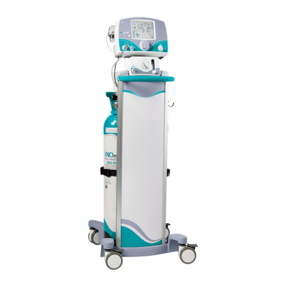
(Delivery System)
Pocket Guide
Series 3 software
Automated Pre-Use Procedure
®
Integrated Pneumatic Backup INOMAX
Delivery
Transport Regulator/Cap Assembly
Oxygen Dilution Chart
INOMAX Cylinder Duration Chart
Circuit Connection Diagrams
Changing INOMAX Cylinders
High Calibration Connection Diagrams
INOmax DS
Disposable Adapters
IR
For 24 Hour Assistance
Call 1-877-566-9466
Part No. 20751 Rev-01
2014-08
Advertisement
Table of Contents

Subscribe to Our Youtube Channel
Related Manuals for Mallinckrodt INOmax DSIR


Summary of Contents for Mallinckrodt INOmax DSIR
- Page 1 (Delivery System) Pocket Guide Series 3 software Automated Pre-Use Procedure ® Integrated Pneumatic Backup INOMAX Delivery Transport Regulator/Cap Assembly Oxygen Dilution Chart INOMAX Cylinder Duration Chart Circuit Connection Diagrams Changing INOMAX Cylinders High Calibration Connection Diagrams INOmax DS Disposable Adapters For 24 Hour Assistance Call 1-877-566-9466 Part No.
- Page 2 IMPORTANT: This guide is provided as a convenience and for general information only. Do not use this product without clearly and thoroughly understanding the most recent revision of the INOmax DS ® Operation Manual. The Operation contained in this guide. Part No.
- Page 3 Mallinckrodt, the “M” brand mark and the Mallinckrodt Pharmaceuticals logo are trademark of a Mallinckrodt company. Other brands are trademarks of a Mallinckrodt company or their respective owner. ©2016 Mallinckrodt Part No. 20751 Rev-01 2014-08...
-
Page 4: Table Of Contents
Contents Automated Pre-Use Checkout ..............5 Integrated Pneumatic Backup INOMAX Delivery .........8 Transport Regulator/Cap Assembly ............10 Oxygen Dilution Chart ................14 INOMAX Cylinder 88-size Duration Chart ..........15 INOMAX Cylinder D-size Duration Chart............16 Connection to Various Breathing Systems ..........17 Acutronics Medical Systems AG Fabian +nCPAP Evolution ....18 Acutronics Medical Systems AG Fabian HFO ........ -
Page 5: Automated Pre-Use Checkout
Pre-Use Checkout Automated Pre-Use Checkout 1. Turn INOmax DS ON, verify speaker function. Note: A low range calibration automatically starts following the self test. A Pre-Use wizard will be displayed on the main screen, which will provide step-by-step instructions to complete the automated Pre-Use procedure. - Page 6 Pre-Use Checkout Part No. 20751 Rev-01 2014-08...
- Page 7 Pre-Use Checkout (Intentionally left blank) Part No. 20751 Rev-01 2014-08...
-
Page 8: Integrated Pneumatic Backup Inomax Delivery
Integrated Pneumatic Backup INOMAX Delivery Note: Use the integrated pneumatic backup function only for a short time, until a replacement delivery system can be obtained. The INOblender can also be used as a backup. If the main delivery system fails, the INOmax DS has an integrated pneumatic backup delivery function that allows the patient to remain connected to the ventilator. - Page 9 Integrated Pneumatic Backup INOMAX Delivery The main screen: · Indicates that backup delivery is on and that the set dose is turned off. · Displays the estimated dose that the patient should be · Displays the NO concentration table Note: If the injector module is not functioning, the estimated backup dose graphic will be inactive.
-
Page 10: Transport Regulator/Cap Assembly
Cap Assembly WARNING: • A new INOMAX cylinder and regulator must be purged before use to ensure the patient does not receive an excess level of NO and the INOMAX cylinder for more than one hour will result in interruption of INOMAX delivery. Caution: When using the Transport Regulator/Cap Assembly (PN 10022) ensure the cap is in place on the cylinder and the infrared cable is connected to the infrared... - Page 11 Cap Assembly Step Two Connect the INOMAX regulator hose to one of the INOMAX inlets on the back of the INOmax (see Figure 3). Figure 3 Step Three Connect the Infrared cable from the Transport Regulator/Cap Assembly to the back of the INOmax (see Figure 4).
- Page 12 Cap Assembly Step Four Place the Cap Assembly over the INOmeter (see Figure 5). Note: Be sure to align the keyway inside the Cap Assembly with the iButton on the INOmeter (see Figure 5 and 6). iButton The electrical cord exits the cap directly above the iButton...
- Page 13 Cap Assembly Final Set-up Diagram The following diagram and photo illustrates all of the components connected. Additional Information Communication will take place between the INOmax DS and the INOmeter after the boot up phase of the INOmax DS is complete. Note: Cylinder icons are not visible and the dose control button will remain inactive until the INOmax DS recognizes an...
-
Page 14: Oxygen Dilution Chart
Oxygen Dilution Chart For delivery with 800 ppm cylinder of Set FiO 1.00 0.21 0.40 0.79 0.99 0.20 0.39 0.78 0.98 0.20 0.38 0.76 0.19 0.36 0.72 0.90 Actual FiO Caution FiO less than 21% Please Note: The calculations on this chart have been determined based on an 800 ppm cylinder of INOMAX (nitric oxide) for inhalation. -
Page 15: Inomax Cylinder 88-Size Duration Chart
Duration Chart INOMAX Cylinder 88-Size For an 88-Size 800 ppm Cylinder Concentration* 39 Days 19.5 Days 9.8 Days 4.9 Days 19.4 Days 9.7 Days 4.8 Days 2.4 Days 9.6 Days 4.8 Days 2.4 Days 1.2 Days 4.7 Days 2.3 Days 1.2 Days 14 Hours 2.2 Days... -
Page 16: Inomax Cylinder D-Size Duration Chart
Duration Chart INOMAX Cylinder D-Size 5 L/min 10 L/min 20 L/min 40 L/min 7.0 Days 3.5 Days 1.8 Days 21 Hours 3.5 Days 1.7 Days 21 Hours 10.5 Hours 1.7 Days 20.7 Hours 10.3 Hours 5.2 Hours 20 Hours 10 Hours 5 Hours 2.5 Hours 9.5 Hours... -
Page 17: Connection To Various Breathing Systems
Circuit Connection Diagrams Proper use of these products depends on careful reading and understanding of labeling and instructions. Please refer to the INOmax DS and INOblender operation manuals for guidance. Also for use. INOmax DS Warnings: • INOmax DS subtracts gas from the breathing circuit via the some ventilators. -
Page 18: Acutronics Medical Systems Ag Fabian +Ncpap Evolution
Circuit Connection Diagrams Acutronics Medical Systems AG Fabian 1. Fabian+ nCPAP Evolution 8. 22F X 15M Adapter 3. Injector Module Electrical Cable 10. Inspiratory Breathing Circuit Hose 4. INOmax DS 11. Gas Sample Tee 5. NO/N Injector Tube 12. Patient Wye 6. -
Page 19: Acutronics Medical Systems Ag Fabian Hfo
Circuit Connection Diagrams Acutronics Medical Systems AG Fabian HFO 1. Fabian HFO Ventilator 9. 22F X 15M Adapter 3. Injector Module Electrical Cable 11. Inspiratory Breathing Circuit Hose 4. INOmax DS 12. Gas Sample Tee 5. NO/N Injector Tube 13. Patient Wye 6. -
Page 20: A-Plus Medical Babi-Plus Bubble Cpap
Circuit Connection Diagrams A-Plus Medical Babi-Plus Bubble CPAP 1. Oxygen Source 9. Tee Adapter 2. Oxygen Tubing 10. Breathing Circuit 3. Pressure Relief Manifold 4. Injector Module 12. NO/N Injector Tube 5. Temperature Probe 13. Injector Module Electrical Cable 6. 90 Degree Sample Port Adapter 14. - Page 21 Circuit Connection Diagrams (Intentionally left blank) Part No. 20751 Rev-01 2014-08...
-
Page 22: Bagging Systems While Using The Injector Module
Circuit Connection Diagrams Bagging Systems While Using the Injector Module the following steps should be taken for use with the manual resuscitator bags: • Use the smallest bag adequate to deliver the desired tidal volume. • Oxygen tubing lengths greater than 72 inches should not be used. - Page 23 Circuit Connection Diagrams 1. O 2 Flowmeter (wall outlet or cylinder) 2. O 2 Tubing 3. 15M X 4.5 mm Adapter 4. 22M/15F X 22M/15F Adapter 5. Injector Module 6. 15M X 4.5 mm Adapter 7. O 2 Tubing 8. O 2 Tubing Sample Tee 10.
-
Page 24: Bunnell Life Pulse High Frequency Ventilator Circuit
Circuit Connection Diagrams WARNING: • Part No. 20751 Rev-01 2014-08... - Page 25 Circuit Connection Diagrams Bagging Systems While Using the Injector Module 1. O Flowmeter 8. Pressure Gauge 2. Injector Module Electrical Cable 9. 15M X 4.5mm Adapter 3. NO/N Injector Tube 10. Injector Module 11. 22M/15F X 22M/15F Adapter 5. O Tubing 12.
- Page 26 Circuit Connection Diagrams High Frequency Ventilator Circuit WARNING: • The INOmax DS patient to avoid NO delivery transiently exceeding the ventilation as soon as the catheter is removed from the airway. This will limit the extent of over delivery above the NO set dose.
- Page 27 Circuit Connection Diagrams 1. INOmax DS 8. Sample Tee 2. Bunnell Life Pulse 9. Patient Box 10. One-Way Valve 11. Injector Module 5. Conventional Ventilator 12. NO/N Injector Tube 6. Life Port Adapter 13. Injector Module Electrical Cable 7. Endotracheal Tube Part No.
-
Page 28: Connecting Inomax Ds
Circuit Connection Diagrams Connecting INOmax DS Sample Tee to the 1. From Patient Box 2. Cut Green tube at midpoint (approximately six inches from the Life Port Adapter) 3. Patient Gas Sample Line with 4. Insert Sample Tee 5. Life Port Adapter 6. -
Page 29: Circle Anesthesia System
Circuit Connection Diagrams Circle Anesthesia System 1. Patient Gas Sample Line with 8. Absorber Inspiratory Port 9. Absorber 2. Patient Gas Sample Line 10. Injector Module Input Connection a. Injector Module Input End 3. INOmax DS b. Injector Module Output End 4. -
Page 30: Löwenstein Leoni-Plus Ventilator
Circuit Connection Diagrams 1. Patient wye 9. Injector Module 2. Dräger Babylog VN500 / Leoni-plus Ventilator 10. One-Way Valve 3. Ventilator Expiratory Port 4. Ventilator Inspiratory Port 5. Patient Gas Sample Line Input Connection 6. INOmax DS 14. Patient Gas Sample Line 7. - Page 31 Circuit Connection Diagrams Fisher & Paykel Bubble CPAP 1. Oxygen Source 10. F/P Inline Infant Nebulizer Kit 2. Oxygen Tubing (RT010) Adapter 3. Bubble CPAP Pressure Manifold 11. Breathing Circuit 4. 22F X 15M Adapter 5. 22M/15F X 22M/15F Adapter 13.
- Page 32 Circuit Connection Diagrams Fisher & Paykel Infant Circuit Nasal Cannula 9. Injector Module Electrical Cable 2. INOmax DS 10. NO/N Injector Tube 3. Oxygen Source 4. Oxygen Tubing 12. Breathing Circuit 5. 22F X 15M Adapter 13. Temperature Probe 6. Injector Module 14.
- Page 33 Circuit Connection Diagrams 10. Breathing Circuit 2. INOmax DS 11. Temperature Probe 3. Oxygen Source 12. Gas Sample Tee 4. Breathing Circuit Hose 13. 22M/15F X 22M/15F Adapter 14. 22 mm ID X 22 mm ID Cuff Adapter 5. Injector Module 6.
-
Page 34: Hamilton Arabella Nasal Cpap
Circuit Connection Diagrams Hamilton Arabella Nasal CPAP 1. Arabella 9. Heated Delivery Circuit 3. INOmax DS 10. Temperature Probe 11. Universal Generator 4. NO/N Injector Tube 5. Injector Module Electrical Cable 12. Arabella Sample Tee 6. Injector Module 13. 90 Degree Sample Port Adapter 7. -
Page 35: Icu Ventilator Circuit
Circuit Connection Diagrams ICU Ventilator Circuit 1. Patient Wye 3. Ventilator 4. Ventilator Expiratory Port 5. Ventilator Inspiratory Port 6. Patient Gas Sample Line Input Connection 7. INOmax DS 8. NO/N Injector Tube Front Panel Connection a. Injector Module 9. Injector Module Electrical Cable Front Panel Connection b. -
Page 36: With A Filtered Circuit
Circuit Connection Diagrams Oscillatory Ventilator with a Filtered Circuit a. Injector Module b. 22F Inlet c. 22M / 15F Outlet Part No. 20751 Rev-01 2014-08... - Page 37 Circuit Connection Diagrams 10. Paw Limit Valve Control 1. Sensormedics 3100A/B Ventilator 11. Filter 2. Ventilator Outlet 3. 22M Adapter 4. Injector Module 14. Bias Flow Tube 5. Injector Module Electrical Cable Connection 16. 90 Degree Sample Port Adapter 6. INOmax DS 17.
-
Page 38: With A Rigid Or Flexible Circuit
Circuit Connection Diagrams Ventilator with a Rigid or Flexible Circuit a. Injector Module b. 22F Inlet c. 22M / 15F Outlet 1. Sensormedics 3100A/B Ventilator 2. Ventilator Outlet 11. Patient Gas Sample 3. 22M Adapter 4. Injector Module 12. 90 Degree Sample 5. -
Page 39: Sle Life Support Sle5000
Circuit Connection Diagrams Note: • Validated for use outside of the United States. • A one-way valve is not required for use during high frequency ventilation mode. 1. Patient Wye 7. Injector Module 8. 22F X 15M Adapter 3. SLE5000 4. -
Page 40: Spontaneous Breathing Patient On A Mask Circuit
Circuit Connection Diagrams Spontaneous Breathing Patient on a Mask Circuit 1. O Tubing 10. One-Way Valve 2. 15M X 4.5 mm Adapter 11. Sealed Face Mask 3. 22M/15F X 22M/15F Adapter 12. One-Way Valve 4. Breathing Circuit Tee 5. Breathing Circuit Bag 14. -
Page 41: Spontaneous Breathing Patient On A Nasal Cannula
Circuit Connection Diagrams Spontaneous Breathing Patient on a Nasal Cannula The INOmax DS can be used with nasal cannula to deliver rate as low as 2 L/min. WARNING: Do not use the INOmax DS backup mode with 1. O Flowmeter 7. - Page 42 Circuit Connection Diagrams 10. Temperature Probe Connector 11. Second Temperature Probe Connector 2. INOmax DS 12. Comfort Flo Cannula 3. Injector Module 13. Injector Module Electrical Cable 4. System Pressure Relief Valve 14. NO/N Injector Tube 5. Air/Oxygen Blender or Oxygen Blender 15.
-
Page 43: Transport Ventilator Circuit
Circuit Connection Diagrams Transport Ventilator Diagram 1. Patient Wye 7. Ventilator Inspiratory Port 2. Expiratory Breathing Circuit Hose 8. 22M/15F X 22M/15F Adapter 3. Patient Gas Sample Line with 9. Injector Module Electrical Cable 10. NO/N Injector Tube 4. Ventilator Expiratory Valve 11. - Page 44 Circuit Connection Diagrams 1. PEEP/Exhalation Valve 7. Ventilator Inspiratory Port 2. Patient Wye 8. 22M/15F X 22M/15F Adapter 3. Circuit Hose 9. Injector Module Electrical Cable 4. Patient Gas Sample Linewith 10. NO/N Injector Tube 11. Injector Module 5. Ventilator 12.
- Page 45 Circuit Connection Diagrams (Intentionally left blank) Part No. 20751 Rev-01 2014-08...
-
Page 46: Vapotherm 2000I
Circuit Connection Diagrams Vapotherm 2000i 1. INOmax DS 9. 15M x 4.5mm Adapter 2. O Flowmeter 10. Vapotherm 2000i 3. O Tubing 11. Patient Delivery Tube 4. 15M x 4.5mm Adapter 12. O Tubing Sample Tee 5. 22M/15F x 22M/15F Adapter 13. -
Page 47: Vapotherm Precision Flow
Vapotherm Precision Flow. It is recommended that after an NO setting • Follow all manufacturer instructions for connection to the Vapotherm Precision Flow. 1. Patient Gas Sample Line 2. INOmax DSIR 3. Precision Flow Unit 4. Injector Module 5. Patient Delivery Tube 6. -
Page 48: Viasys Infant Flow Cpap System; Cardinal Airlife Ncpap System
Circuit Connection Diagrams 1. INOmax DS 2. Heated Delivery Circuit 3. Infant Flow System 9. 22F X 15M Adapter 4. Infant Flow Generator 10. Injector Module 11. NO/N Injector Tube 5. Sample Tee 6. Temperature Probe 12. Injector Module Electrical Cable Part No. -
Page 49: Viasys Infant Flow Sipap
Circuit Connection Diagrams Viasys Infant Flow SiPAP 8. Heated Delivery Circuit 1. INOmax DS 2. Abdominal Respiratory Sensor 10. 22F X 15M Adapter 3. Transducer Interface 11. Injector Module 4. Infant Flow SiPAP 12. Injector Module Electrical Cable 5. Infant Flow Generator 13. -
Page 50: Inoblender Circuit Connection
INOblender Circuit Connection Diagram INOblender Warnings: • The purge procedure must be followed to help ensure NO before the manual resuscitator bag is connected to the patient. The manual bag should be squeezed continuously during use to avoid NO building up in the bag. If the bag is not squeezed removed from the patient and the purge procedure performed before continuing. - Page 51 INOblender Circuit Connection Diagram INOblender Connection to the Fisher & Paykel Neopuff Resuscitator Oxygen Source INOMAX Inlet 1. Oxygen Source 2. Neopuff 3. T-Piece Circuit (with Duckbill Port) 4. Patient Connection 5. Temperature Probe 8. Oxygen Tubing 9. INOblender 10. INOMAX Inlet Part No.
-
Page 52: Changing Inomax Cylinders
Changing INOMAX Cylinders Changing INOMAX Cylinders WARNING: • A new INOMAX cylinder and regulator must be purged before use to ensure the patient does not receive an excess level of NO the INOMAX cylinder for more than one hour will result in interruption of INOMAX delivery. - Page 53 Changing INOMAX Cylinders B. Perform high pressure leak test. C. Purge the high pressure hose. D. Connect the pressure hose. Part No. 20751 Rev-01 2014-08...
- Page 54 Changing INOMAX Cylinders may activate the “Two Cylinders Open” alarm until the empty Note: If using the INOmax DS Transport Regulator/Cap Assembly, transfer the cap from the exhausted INOMAX cylinder to the new INOMAX cylinder at this time; the “Cylinder Not Detected”...
- Page 55 Changing INOMAX Cylinders (Intentionally left blank) Part No. 20751 Rev-01 2014-08...
-
Page 56: High Calibration Connection Diagrams
High Calibration Connection Diagrams Connection Diagram for NO and NO High Range Calibration INOmax DS 6a. If the pressure is in the red or black 1. Cylinder Cap zone (0-25 psig) select another INOcal 2. Regulator Seal cylinder. 3. Regulator 7. - Page 57 High Calibration Connection Diagrams Calibration Setup for O High Range Calibration 1. 100% O Source 2. O Tubing 3. 15M x 4.5mm I.D. Adapter 4. Gas Sample Tee Part No. 20751 Rev-01 2014-08...
-
Page 58: Inomax Ds Ir Disposable Adapters
INOmax DS Disposable Adapters INOmax DS Patient Circuit Disposables (Note: Graphics not actual size) Adapter, Adapter, 22F X 15M 15M Fits 4.5mm ID Tubing Adapter, 22M/15F X 22M/15F Adapter, Cuff, 22mm ID X 22mm ID Adapter, Gas Sample Tee Adapter, 90 degree Sample Port Bunnell Life Pulse Disposable Disk Filter, 0.5 micron Adapters Convenience Pack... - Page 59 INOmax DS Disposable Adapters One-way Valve, 22F X 22M Patient Gas Sample Line with Pediatric Extension, Sample Tee, O Tubing 15 mm (6 inches) Sensormedics 3100A/B Water Separator Cartridge Filtered Circuit Disposable Adapters Convenience Pack Part No. 20751 Rev-01 2014-08...
- Page 60 Part No. 20751 Rev-01 2014-08...
Need help?
Do you have a question about the INOmax DSIR and is the answer not in the manual?
Questions and answers