
Subscribe to Our Youtube Channel
Related Manuals for Nortel Passport 4460


Summary of Contents for Nortel Passport 4460
- Page 1 Part No. 205677-F Rev 00 July 2003 4555 Great America Parkway Santa Clara, CA 95054 Reference for Passport 4460 Hardware...
- Page 2 In the interest of improving internal design, operational function, and/or reliability, Nortel Networks Inc. reserves the right to make changes to the products described in this document without notice. Nortel Networks Inc. does not assume any liability that may occur due to the use or application of the product(s) or circuit layout(s) described herein.
- Page 3 Warranty Period, to perform substantially in accordance with the documentation, provided such failure can be recreated by Nortel in an unmodified version of the software program, or if Nortel is unable to correct such failure the software program and documentation may be returned and the license fee paid will be refunded, or (ii) replace any diskette not meeting Nortel’s “Limited Warranty”...
- Page 4 Canada requirements only Canadian Department of Communications Radio Interference Regulations This digital apparatus (Passport 4460) does not exceed the Class A limits for radio-noise emissions from digital apparatus as set out in the Radio Interference Regulations of the Canadian Department of Communications.
- Page 5 FCC Part 68 compliance statement This equipment complies with Part 68 of FCC Rules. All direct connections to telephone network lines must be made using standard plugs and jacks compliant with FCC Part 68. Please note the following: Reference for Passport 4460 Hardware...
- Page 6 FCC. If you experience trouble with the unit, please contact the Nortel Networks Technical Solutions Center in your area for service or repairs. Repairs should be performed only by service personnel authorized by Nortel Networks.
- Page 7 3A/1.5A Courant d’Accès: 3A/1.5A Frequency: 47-63 Hz Frequenz: 47-63 Hz Fréquence: 47-63 Hz dc units dc Geraete dc appareils Input Voltage: 36-72 Vdc Nennspannung: 36-72 V Voltage d’Accès: 36-72 V Input Current: Nennstrom: Courant d’Accès: Reference for Passport 4460 Hardware...
- Page 8 30 days of purchase to obtain a credit for the full purchase price. “Software” is owned or licensed by Nortel Networks, its parent or one of its subsidiaries or affiliates, and is copyrighted and licensed, not sold. Software consists of machine-readable instructions, its components, data, audio-visual content (such as images, text, recordings or pictures) and related licensed materials including all whole or partial copies.
- Page 9 (for DoD entities). Customer may terminate the license at any time. Nortel Networks may terminate the license if Customer fails to comply with the terms and conditions of this license. In either event, upon termination, Customer must either return the Software to Nortel Networks or certify its destruction.
- Page 10 205677-F Rev 00...
-
Page 11: Table Of Contents
AC Power Supply for Passport 4460 ........ - Page 12 Contents T1/FT1 DSU/CSU Adapter Module ........44 E1/FE1 G.703/G.704 Adapter Modules (RJ and BNC) .
- Page 13 Connecting the Passport 4460 Unit ........
- Page 14 1.544 Mbits/s AND/OR SUBRATE DIGITAL SERVICES ....136 Passport 4460 Base Module (Part Number 205683-A) ....137 WAN Modules Specifications .
- Page 15 Index ............149 Reference for Passport 4460 Hardware...
- Page 16 Contents 205677-F Rev 00...
-
Page 17: About This Manual
This manual explains how to unpack, situate, cable, and power up your Passport* 4460 unit to get it operational. It provides technical reference information for all of the hardware elements of the Passport 4460 unit, including their features, installation instructions, and configuration possibilities. - Page 18 About this Manual If you purchased a Nortel Networks service program, contact one of the following Nortel Networks Technical Solutions Centers: Technical Solutions Center Telephone Europe, Middle East, and Africa +44 (0)20-8920-4618 North America (800) 4NORTEL or (800) 466-7835 Asia Pacific...
-
Page 19: The Passport 4460 Unit
39 What is the Passport 4460 Unit? The Passport 4460 unit is a member of the Passport 4400 series of Multiservice Access Switches. These switches support Voice over Frame Relay (VoFR) and Voice over IP (VoIP). They also integrate voice, fax, modem, video, local area network (LAN), and legacy-data traffic over a single wide area network (WAN) link. - Page 20 SYSTEM STATUS Expansion Slots WAN Slots The Passport 4460 unit is available with either an AC or DC power supply. The AC version offers an attachment to an RPSU (Redundant Power Supply Unit) (see page 37). Refer to page 36 for information on the Passport 4460 DC unit.
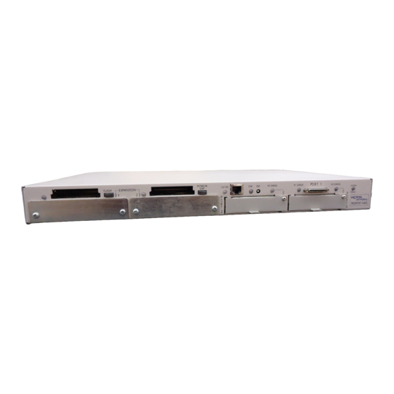
- Page 21 Chapter 1 The Passport 4460 Unit 21 These illustrations show the front and back view of the Passport 4460 AC unit. RESERVED MGNT SERVICE PORT 115/230V PORT EXPANSION STAT PORT 1 10/100 P2 STATUS P1 STATUS P3 STATUS SYSTEM STATUS...
-
Page 22: Passport 4460 Unit Features
22 Chapter 1 The Passport 4460 Unit Passport 4460 Unit Features The Passport 4460 unit offers various network features supporting a number of multi-service concepts. These features offer diverse networking options, regardless of the WAN technology used. These features consist of the following: Power Supplies: •... -
Page 23: Ac Power Supply For Passport 4460
Chapter 1 The Passport 4460 Unit 23 AC Power Supply for Passport 4460 The Passport 4460 AC unit has the following connectors located on the front panel: • 3-prong power connector (115/230 VAC) • Management port (DB-9) (see Chapter 7, “Port Connections for the Passport 4460”) -
Page 24: Redundant Power Supply For Passport 4460
24 Chapter 1 The Passport 4460 Unit Redundant Power Supply for Passport 4460 The following connectors are located on the front of the Passport 4460 AC unit designed for Redundant Power: • 3-prong power connector (115/230 VAC) • Redundant Power Supply Connector •... - Page 25 Chapter 1 The Passport 4460 Unit 25 • One built-in serial port for either WAN or data connection 10/100BASE-T Port Serial Port Flash Slot PCMCIA Slot EXPANSION STAT 10/100 P1 STATUS PORT 1 P3 STATUS SYSTEM P2 STATUS STATUS Expansion Slots...
-
Page 26: Checking The Package Contents
26 Chapter 1 The Passport 4460 Unit Checking the Package Contents Because the Passport 4460 unit has optional configurations available, check the packing list against the package contents to ensure you have received the proper equipment you ordered for your installation. Report any damage to the shipping carrier. - Page 27 Chapter 1 The Passport 4460 Unit 27 If you ordered a... Order Code You should have received a... Passport 4460 DC Base PA4202001 • Base unit with DC power supply. Unit (without power cord) • Modules ordered - installed (varies according to network requirements) •...
-
Page 28: Considerations For Installing The Unit
28 Chapter 1 The Passport 4460 Unit Considerations for Installing the Unit A Passport 4460 unit is typically installed in one of two places: either on a surface (such as a table or desk) in a lab or office, or in an equipment rack (see the “Rackmount Installation”... -
Page 29: Rackmount Installation
43.8 cm (17.25 inches) 33 cm (13.0 inches) Rackmount Installation For installing the Passport 4460 unit in a 19-inch rack, use the accessory kit provided. Each accessory kit contains the following parts: • Four screws • Two mounting ears (L-shaped brackets) The cabinet manufacturer should have provided you with the necessary hardware for attaching the L-shaped bracket to the cabinet. - Page 30 Make sure each unit is properly grounded. To install your unit into a cabinet: Fasten the L-shaped brackets onto the sides of the Passport 4460 unit. Place the unit in the cabinet making sure to line up the holes on the L-shaped bracket with the holes in the frame of the cabinet.
- Page 31 Chapter 1 The Passport 4460 Unit 31 Fasten the L-shaped bracket onto the frame of the cabinet. Note: The L-shaped side brackets in the cabinet are adjustable. If your cabinet has a door, you may have to slide the brackets further into the cabinet to allow the door to close.
-
Page 32: Setting Up The Passport 4460
32 Chapter 1 The Passport 4460 Unit Setting Up the Passport 4460 Once you have installed your Passport 4460 unit, you must do the following to set your unit up for operation: Installing the PCMCIA Flash Module Insert the PCMCIA Flash module into the Flash slot on the Passport 4460. This module is used for downloading system configuration software. -
Page 33: Connecting The Workstation
Connecting the Workstation Connect one end of the management cable to the serial port of the PC workstation. Connect the other end to the management port of the Passport 4460. For additional information on management port connections, go to Chapter 7. - Page 34 If a power cord is not supplied with your AC unit or not available with the Sales order, make sure that any power cord used with the Passport 4460 unit meets the ratings of 125 Volts and 3 Amps or 254 Volts and 1.5 Amps.
- Page 35 Chapter 1 The Passport 4460 Unit 35 Warning: Countries other than U.S.A. You should have received a power cord with a two-prong power connector and a green-with-yellow stripe ground wire as shown in the examples below. If the power outlet is not grounded, contact an electrician to connect the green-with-yellow stripe wire to a fixed earth grounding point.
-
Page 36: Connecting The Dc Unit
The ground is attached to the screw at the side of the main power connector on the unit. The DC version of the Passport 4460 unit has an external terminal block that is connected to the main power connected at the front of the unit. -
Page 37: Connecting A Passport 4460 Unit With Redundant Power
(Redundant Power Supply Unit) for a power redundant solution. It is the same chassis as the Passport 4460 AC unit except that it has a connector at the center-front of the chassis that allows for the attachment to the RPSU. - Page 38 Note: When using the Passport 4460 unit and redundant power supply unit (RPSU), make sure the Passport 4460 unit is either stacked on top of the RPSU or beside the RPSU. Do not stack the RPSU on top of the Passport 4460 unit.
-
Page 39: Replacing Hardware Modules
Perform a default reset to set the configuration to factory defaults. Use the Mass Deployment and Reporting Tool Downloader to reload the modified configuration file to the defaulted Passport 4460. Configure the ports on the new module, as desired. Use of the Mass Deployment and Reporting Tool is optional. The alternative is to manually re-configure the unit after performing the default reset. - Page 40 40 Chapter 1 The Passport 4460 Unit 205677-F Rev 00...
-
Page 41: Chapter 2 Wan Adapter Modules
Serial Module page 53 The base module of the Passport 4460 unit has two modular WAN slots, capable of housing any two optional WAN adapter modules. These slots are located on the rear (module side) of the chassis, at the lower right side of the unit. -
Page 42: Installing/Removing Wan Adapter Modules
Carefully slide the adapter module into Port 2 or Port 3, located at the lower right side of the Passport 4460 back panel. Make sure that the module is pushed all the way in, so it firmly mates with the connector at the rear of the slot. - Page 43 4460” • Appendix B, “Regulatory Compliance and Telephone Company Requirements” After the modules are in place and the system is operating, refer to the software documentation for configuration information (see “Product documentation” on page 17). Reference for Passport 4460 Hardware...
-
Page 44: T1/Ft1 Dsu/Csu Adapter Module
44 Chapter 2 WAN Adapter Modules T1/FT1 DSU/CSU Adapter Module The T1/FT1 DSU/CSU Adapter Module provides a direct T1 or fractional T1 connection to a Passport unit or any other compatible device. The T1/FT1 DSU/CSU Adapter Module is compliant with the ANSI T1.231 standards Note: This module is designed to accept an RJ-48 connector;... -
Page 45: E1/Fe1 G.703/G.704 Adapter Modules (Rj And Bnc)
E1/FE1 G.703/G.704 (RJ) Adapter Module with DSU functionality at 120 ohms, with an RJ-48 physical connector • E1/FE1 G.703/G.704 (BNC) Adapter Module with DSU functionality at 75 ohms, with an external balun to provide BNC connectivity Reference for Passport 4460 Hardware... - Page 46 46 Chapter 2 WAN Adapter Modules The integrated DSU/CSU functionality allows direct connection to the E1 network, rather than connecting via an external adapter. This solution simplifies connection to an E1 ATM carrier. Both Port 2 and Port 3 can support the E1/FE1 G.703/G.704 (BNC) adapter module.
- Page 47 Lights when the E1 port has received a remote alarm from the E1 network Loop Amber Lights when the E1 interface is placed in loopback mode Sync Green Lights when the E1 port is synchronized with the E1 network Reference for Passport 4460 Hardware...
-
Page 48: Isdn Bri Adapter Modules (S/T And U Interface)
48 Chapter 2 WAN Adapter Modules For additional information, see the following: • Chapter 6, “Cables” • Appendix A, “Indicators” • Appendix B, “Regulatory Compliance and Telephone Company Requirements” After the modules are in place and the system is operating, refer to the software documentation for configuration information (see “Product documentation”... - Page 49 D-channel (control and signal information). Note: During diagnostic testing, the indicator blinks on and off. However, it does not indicate data transfer until you have configured and enabled software services. Reference for Passport 4460 Hardware...
- Page 50 50 Chapter 2 WAN Adapter Modules For additional information, see the following: • Chapter 6, “Cables” • Appendix A, “Indicators” • Appendix B, “Regulatory Compliance and Telephone Company Requirements” After the modules are in place and the system is operating, refer to the software documentation for configuration information (see “Product documentation”...
- Page 51 “Indicators” • Appendix B, “Regulatory Compliance and Telephone Company Requirements After the modules are in place and the system is operating, refer to the software documentation for configuration information (see “Product documentation” on page 17). Reference for Passport 4460 Hardware...
-
Page 52: 56/64K Dsu/Csu Module
52 Chapter 2 WAN Adapter Modules 56/64K DSU/CSU Module The 56/64K DSU/CSU module supports the Digital Data Service (DDS) without the secondary signaling channel. Both Port 2 and Port 3 can support the 56/64K DSU/CSU module. Note: This module is designed to accept an RJ-48 connector; however, it is compatible with an RJ-45 cable connector. -
Page 53: Serial Module
The Serial Module must be inserted into the unit with the component side up. Indicator SERIAL WAN Note: Pin assignments and configuration information are the same as for the Serial Port located on the Passport 4460 Base Module. This information is located in Chapter 7 of this manual. Reference for Passport 4460 Hardware... - Page 54 54 Chapter 2 WAN Adapter Modules The Serial Module indicator light is tri-colored and lights up (green = OK; red = failure; amber = no signal) when the serial interface is operating. Status Definition Green Everything is functioning; indicates any of the following: •...
-
Page 55: Expansion Modules
77 Expansion modules provide customizing and expansion of services for the Passport 4460. The unit can accommodate two expansion modules. Any expansion module combination is supported. These modules fit into the slots located at the rear of the chassis, at the lower left side of the unit. -
Page 56: Installing/Removing The Expansion Module
Warning: Do not remove or insert modules while the Passport 4460 is operating. To do so could result in damage to the Passport 4460 unit or network interruption. To ensure a proper fit of the expansion module, the expansion slot has a groove on each side into which the module can easily slide. - Page 57 4460” • Appendix B, “Regulatory Compliance and Telephone Company Requirements” After the modules are in place and the system is operating, refer to the software documentation for configuration information (see “Product documentation” on page 17). Reference for Passport 4460 Hardware...
-
Page 58: T1 Voice Expansion Module
Digital Voice Expansion Modules (maximum of three) • Maximum of two T1 Voice Expansion Modules per Passport 4460 unit, providing support for up to 48 voice channels The T1 Voice Expansion Module is compliant with the ANSI T1.231 standards... -
Page 59: E1 Voice Expansion Module
Expandable to 30 E1 voice channels (in six channel increments) with optional Digital Voice Expansion Modules (maximum of four) • Maximum of two E1 Voice Expansion Modules per Passport 4460 unit providing support for up to 60 voice channels Pin 1... - Page 60 60 Chapter 3 Expansion Modules • Appendix B, “Regulatory Compliance and Telephone Company Requirements” • Appendix C, “Specifications” After the modules are in place and the system is operating, refer to the software documentation for configuration information (see “Product documentation” on page 17).
-
Page 61: Digital Voice Expansion Module
T1 Voice Expansion Module in the X4 (DSP4) position after X2 (DSP2) and X3 (DSP3) have already been mounted. X5 (DSP5) is available only on the E1 Voice Expansion Module. Digital Voice Expansion Module T1Voice Module Reference for Passport 4460 Hardware... -
Page 62: Fxs Voice Expansion Module (Dual And Quad Channel)
Short loop applications (up to 3,000 feet) • Loop Start • Ground Start (enables direct connectivity to PBX CO trunk lines) • 25 Hz and 50 Hz ringing frequency • Dial Pulse and DTMF detection The Passport 4460 can support two FXS modules. 205677-F Rev 00... - Page 63 Pins 1, 2, 5, 6 Not Connected The illustration below shows a quad channel FXS Voice Expansion Module back panel. Indicators Pin 1 RJ-11 Pin Assignments Two Center Pins Ring Pins 1, 2, 5, 6 Not Connected Reference for Passport 4460 Hardware...
- Page 64 Caution: The FXS Voice Expansion Module is very sensitive to damage from improper handling or wrong settings. These settings should be done when the FXS module is outside the Passport 4460 unit and must be done by a qualified technician.
- Page 65 Chapter 7, “Port Connections for the Passport 4460” • Appendix C, “Voice Module Specifications After the modules are in place and the system is operating, refer to the software documentation for configuration information (see “Product documentation” on page 17). Reference for Passport 4460 Hardware...
-
Page 66: Isdn Bri Voice Expansion Modules - S/T Interface (Single And Dual Port)
66 Chapter 3 Expansion Modules ISDN BRI Voice Expansion Modules - S/T Interface (Single and Dual Port) The ISDN BRI Voice Expansion Module - S/T Interface Module (single and dual port) supports the following: • S/T interface • Two ISDN BRI Voice Expansion Modules supported per unit •... - Page 67 ISDN BRI VOICE S/T RJ-45 Pin Assignments Pin 1 Transmit Data to Network (Tx+) Receive Data from Network (Rx+) Receive Data from Network (Rx-) Transmit Data to Network (Tx-) Pins 1, 2, 7, 8 Not Connected Reference for Passport 4460 Hardware...
- Page 68 68 Chapter 3 Expansion Modules Refer to the following chart for definitions of the ISDN BRI Voice Expansion Module (single and dual port) indicator functions on the Passport 4460 unit. Indicator lights for the ISDN BRI Voice Expansion Module are tri-colored (red, yellow, green).
-
Page 69: 2-Port Serial Data Expansion Module
Both ports can be configured as WAN ports with external DSU/CSU attached. Note: On Passport 4460 units supporting master clocking, only the first of the two ports can supply clock to the backplane. However, both ports can receive clock from the backplane. - Page 70 SERIAL DATA EXPANSION PORT PORT Pin assignments and configuration information are the same as for the serial port for the Passport 4460 base module. This information is located in Chapter 7 of this manual. For additional information, see the following: •...
-
Page 71: 6-Port Serial Data Expansion Module
Port 1 on the base module. You can install as many as two modules in a Passport 4460. A Breakout Panel (214061-A) with an integrated connecting cable is available for the 6-Port Serial Data Expansion Module to support cable connection of the six serial ports. - Page 72 R1 T1 SERIAL 10163EA Note: Serial port pin assignments and configuration information are the same as for the serial port located on the Passport 4460 base module. This information is located in Chapter 6 of this manual. 205677-F Rev 00...
- Page 73 Note: If you need to replace an installed 6-Port Serial Data Expansion Module with a different type of module (such as a 2-Port Serial Data Expansion Module), refer to “Replacing Hardware Modules” on page 39 for important requirements and instructions. Reference for Passport 4460 Hardware...
-
Page 74: Breakout Panel And Cable
74 Chapter 3 Expansion Modules Breakout Panel and Cable A Breakout Panel (214061-A) with an integrated connecting cable is available for the 6-Port Serial Data Expansion Module to support cable connection of the serial ports. The integrated Breakout Panel cable connects to the 160-pin connector on the module. -
Page 75: Alternate Breakout Panel And Cable
This unit provides the same capability as that of the “slimline” breakout panel (part number 214061-A) described “Breakout Panel and Cable” on page This illustration shows a front view of the alternate breakout panel (part number 210873-A) for the 6-port module: 10165EA Reference for Passport 4460 Hardware... - Page 76 76 Chapter 3 Expansion Modules The dimensions of the alternate breakout panel are as follows: Dimensions Width 44.45 cm (17.5 in.) Height 4.445 cm (1.75 in.) Depth 9.525 cm (3.75 in.) The illustration below shows the cable (part number 209133-A) that you use to connect the alternate breakout panel to the 6-port module.
-
Page 77: E&M Voice Expansion Modules (Dual And Quad Channel)
Dial Pulse (10 pps) and DTMF detection and regeneration. The Passport 4400 can support two E&M modules. The illustration below shows a E&M Voice Expansion Module (dual channel) back panel. Indicators Pin 1 E & M VOICE RJ-45 Pin Assignments Reference for Passport 4460 Hardware... - Page 78 78 Chapter 3 Expansion Modules The illustration below shows a E&M Voice Expansion Module (quad channel) back panel. Indicators Pin 1 E & M VOICE RJ-45 Pin Assignments In the 4-wire E&M, T/R is transmit and T1/R1 is receive. The indicator functions for the E&M Voice Expansion Modules (Dual and Quad Channel) are identical.
- Page 79 Chapter 7, “Port Connections for the Passport 4460” • Appendix C, “Specifications” After the modules are in place and the system is operating, refer to the software documentation for configuration information (see “Product documentation” on page 17). Reference for Passport 4460 Hardware...
- Page 80 80 Chapter 3 Expansion Modules 205677-F Rev 00...
-
Page 81: Mb Flash Module
The 16 MB Flash Module contains the latest software configuration for the Passport 4460 unit. Note: To make the Passport 4460 unit operational, the 16 MB Flash Module must have the write protect switch OFF and installed in the unit to provide a download of the system configuration software. -
Page 82: Installing/Removing A Flash Module
Passport 4460 will be inoperable at power up or after any reset. As a safety precaution, the Passport 4460 is designed to reject a Flash module that is not inserted properly. If not inserted properly, the Flash eject button will not pop out, which is an indication that a connection has not been made. - Page 83 Chapter 7, “Port Connections for the Passport 4460” To remove a Flash module: Release the module by pushing in on the Flash eject button located to the right of the slot. Gently pull the module out of the slot. Reference for Passport 4460 Hardware...
-
Page 84: Flash Indicator
84 Chapter 4 16 MB Flash Module Flash Indicator A tri-color Flash indicator provides indications for the functions of the Passport 4460 unit. Refer to the chart below for definitions of indicator status. Flash Indicator EXPANSION STAT PORT 1 10/100... -
Page 85: Pcmcia Expansion Module
PCMCIA Expansion Module The optional PCMCIA expansion module supports IP routing and provides a connection to the Internet for the Passport 4460 unit. The Passport 4460 unit supports type I, II, and type III PCMCIA modules. The PCMCIA expansion module fits into the PCMCIA slot labeled PCMCIA EXP. - Page 86 For information on the PCMCIA expansion module you are using, refer to the User’s Guide included with the module. Warning: Only Nortel Networks-approved PCMCIA expansion modules are supported. The Xircom RealPort Ethernet 10/100 Integrated PC Card is the only card that has been tested and approved. Any other PCMCIA expansion modules installed in the unit may cause damage to the unit and void the warranty.
-
Page 87: Emc Control Clamp
3.7 cm. (1-1/2 inch) from the connector located on the PCMCIA expansion module. The cable must pass through the clamp three times to function properly. Refer to the Installing the EMC Control Clamp manual, for installation instructions. Reference for Passport 4460 Hardware... -
Page 88: Installing/Removing A Pcmcia Expansion Module
Caution: Do not remove or insert a PCMCIA expansion module when the LED indicator is lit as this could cause damage to the equipment. Any PCMCIA module used in the Passport 4460 should comply with relevant regulatory compliances (EMC and, where required, with Safety LVD and/ or telephone company connect requirements). -
Page 89: Pcmcia Indicator
PCMCIA indicator will display the status for the LAN and the PCMCIA module, as defined in the table on page 78. PCMCIA Indicator EXPANSION STAT PORT 1 10/100 P2 STATUS P1 STATUS P3 STATUS SYSTEM STATUS Reference for Passport 4460 Hardware... - Page 90 90 Chapter 5 PCMCIA Expansion Module Indicator Status Definition No LAN connection Red - slow flash Diagnostic mode Red - rapid flash Collision detected on either 10MB or 100MB LAN Red - solid PCMCIA module down (faulty) Yellow - slow flash PCMCIA module initializing Yellow - fast flash 100MB LAN activity...
-
Page 91: Cables
The following tables list the cables available for the various interfaces used in the Passport 4460. Refer to the Reference for Passport 4460 Cables manual for cable diagrams and pin assignment information of the cables referred to in the following tables. - Page 92 92 Chapter 6 Cables Port Interface Order Code CPC Number Part Number Connects to..Serial Ports V.24/ PA4218001 A0668483 206760-A To DCE, DB-25 male (50-pin RS-232 (15 ft.) connector) V.24/ PA4218002 A0668484 206761-A To DTE, DB-25 female RS-232 (15 ft.) V.35 PA4218003 A0668485...
-
Page 93: Cables For Digital Voice Modules
3 feet one end of the cable connects to the 6-port serial data expansion module. The other end connects to the breakout panel. Note: The Breakout Panel is part number 210873-A. The order number is PA4218020. Reference for Passport 4460 Hardware... -
Page 94: F Rev
94 Chapter 6 Cables 205677-F Rev 00... -
Page 95: Port Connections For The Passport 4460
Reset page 107 Connecting the Passport 4460 Unit Note: If you wish to configure the Passport 4460 unit for network use prior to adding cables, refer to Configuring and Operating the Passport 4400. Connection procedures are described in the following pages. Individual procedures depend on the specific site requirements. -
Page 96: Connecting The Management Port
17). Connecting the Management Port The Management Port, located on the front right-hand side of the Passport 4460 unit, is used to connect a PC/CPU (command port) or a modem. This connection is needed for operating the Command Line Interface (CLI), which is used to set and view configuration options. -
Page 97: Direct Connection
Chapter 7 Port Connections for the Passport 4460 97 Direct Connection If the PC and Passport 4460 are in physical proximity to one another, you can directly connect them using the cable supplied with the Passport 4460 (PA4218019), as shown in this diagram:... -
Page 98: Modem Connection
98 Chapter 7 Port Connections for the Passport 4460 Connect one end of the cable to the PC and the other end to the Passport 4460 management port. You may need a 9-pin-to-25-pin RS-232/V.24 serial port adapter or a female-to-female 25-pin adapter to connect the cable to the PC. This adapter is not provided with the unit. -
Page 99: Configuring The Modem Attached To The Passport 4460
Chapter 7 Port Connections for the Passport 4460 99 Configuring the Modem Attached to the Passport 4460 The modem that is attached to the Passport 4460 must be configured for Quiet operations (no result code, no command echo/local echo). You use a terminal emulation program or a dumb terminal to configure the modem. -
Page 100: Testing The Modem Configuration
100 Chapter 7 Port Connections for the Passport 4460 Once the modem is configured, connect it to the Passport 4460 management port. The Passport should now be ready to receive calls. Note: If your modem doesn't support the Hayes AT commands, consult your modem documentation for the procedure for your particular modem. - Page 101 Chapter 7 Port Connections for the Passport 4460 101 Switch Required Setting Description Number Setting Loads Y or Y1 configuration from user- defined nonvolatile memory (NVRAM) Disables command recognition (Dumb Mode) ON = DOWN OFF = UP Use the settings described in the above table, but set the modem to Smart Mode (hardware switch 8 ON [down]).
-
Page 102: Baud Rate
8 to OFF (up). Warning: Incorrect modem settings and/or cabling may cause interruption of service on the Passport 4460 when attempting to dial in. Baud Rate You may set the management port baud rate either from the CLI (via SNMP) or through the boot time debug menu. - Page 103 Chapter 7 Port Connections for the Passport 4460 103 • 50-pin serial data port • Interface determined by cable: RS-232/V.24, V.35, V.36, or X.21 • Mode (DCE or DTE) determined by cable and configuration • Safety approval: BABT A607457 The following illustration shows the location of the serial port.
- Page 104 104 Chapter 7 Port Connections for the Passport 4460 The following illustration displays the pin assignments for the serial port connector. Pin 1 50 Pin Connector 1, 2 Interface Type Indication 3, 28 V.35 Transmit Data 4, 29 V.35 External Receive Data Clock 5, 30 V.35 External Transmit Data Clock...
-
Page 105: Connecting The 10/100Base-T (Ethernet) Port
Connecting the 10/100BASE-T (Ethernet) Port The 10/100BASE-T (Ethernet*) port is used to connect to a local area network (LAN). This port, located on the back of the Passport 4460 unit, connects the unit to the Ethernet. The following illustration shows the location of the LAN port and its connection through the Ethernet. -
Page 106: Verifying Operation
106 Chapter 7 Port Connections for the Passport 4460 An additional 10/100BASE-T port is available through the 10/100BASE-T PCMCIA expansion module using the Crossover LAN cable (part number 207232-A). Refer to Chapter 5, “PCMCIA Expansion Module,” for this connection. If you are using the 10/100BASE-T port and the Xircom RealPort Ethernet 10/100 Integrated PC Card simultaneously, the following requirements must be noted: •... -
Page 107: Reset
“Product documentation” on page 17). The reset button (RST) is located on the rear of the Passport 4460, just above the Port 2 WAN slot. The following illustration shows the location of the reset indicator and reset button. Use a small, pointed object to access the reset button. -
Page 108: Performing A Warm Reset
108 Chapter 7 Port Connections for the Passport 4460 Performing a Warm Reset Note: You do not need to be connected to a Command Line Interface (CLI) terminal to perform the warm reset. To reset the unit and retain the current configuration, press the reset button for one second. -
Page 109: Indicators
Appendix A Indicators There are eight tri-color indicators located on the Passport 4460 base unit. Each WAN adapter and expansion module also has its own set of indicators. The indicators confirm that the unit and modules are operating properly. Each indicator and its functions are described on the following pages. -
Page 110: System Status
110 Appendix A Indicators System Status Refer to the chart below for definitions of the system status indicator functions on the Passport 4460 unit. System Status EXPANSION STAT PORT 1 10/100 P2 STATUS P1 STATUS P3 STATUS SYSTEM STATUS Indicator Type... -
Page 111: Flash
Appendix A Indicators 111 Flash Refer to the chart below for definitions of the PCMCIA Flash module indicator functions on the Passport 4460 unit. Flash Indicator EXPANSION STAT PORT 1 10/100 P2 STATUS P1 STATUS P3 STATUS SYSTEM STATUS Caution: Do not remove or insert a PCMCIA module if the indicator next to the slot is lit as this could cause damage to the equipment. -
Page 112: Pcmcia
112 Appendix A Indicators PCMCIA The PCMCIA indicator light performs functions in accordance with the module that is used. For example, the PCMCIA 10/100BASE-T module indicator light performs the same indicator functions as the built-in 10/100BASE-T module. Refer to the chart on page 113. -
Page 113: 10/100Base-T
Appendix A Indicators 113 10/100BASE-T Refer to the chart below for definitions of the 10/100BASE-T indicator functions on the Passport 4460 unit. 10/100BASE-T Indicator EXPANSION STAT PORT 1 10/100 P2 STATUS P1 STATUS P3 STATUS SYSTEM STATUS Indicator Type Indicator Status... -
Page 114: Reset
114 Appendix A Indicators Reset Refer to the chart below for definitions of the reset indicator functions on the Passport 4460 unit. Reset Reset Indicator Button (STAT) (RST) EXPANSION STAT P1 STATUS PORT 1 P3 STATUS SYSTEM 10/100 P2 STATUS... -
Page 115: Serial Port Indicator
WAN configuration you are using. Refer to the chart below for definitions of the P1 serial port indicator functions on the Passport 4460 unit. Note that the first chart is for sync applications, and the second chart is for async. -
Page 116: P2 And P3 Wan Port Indicators
P2 and P3 WAN Port Indicators Refer to the chart below for definitions of P2 and P3 WAN Port indicator functions on the Passport 4460 unit. The P2 and P3 indicators indicate the physical activity of the module used. Refer to the individual WAN module indicators for the indicator functions of the module you are using. -
Page 117: Adapter Module Indicators (Wan)
Refer to the chart pertaining to each module to check the definitions of the indicators. 56/64K DSU/CSU (WAN) Refer to the chart below for definitions of the 56/64K DSU/CSU WAN module indicator functions on the Passport 4460 unit. Indicators 56K/64K DSU/CSU Test The chart below describes the indicator functions. -
Page 118: Serial Module (Wan)
Serial Module (WAN) Refer to the chart below for definitions of the Serial Module indicator functions on the Passport 4460 unit. The Serial Module indicator is dual color and lights up (green = OK; red = failure) when the serial interface detects data transfer. -
Page 119: T1/Ft1 Dsu/Csu Adapter Module (Wan)
Appendix A Indicators 119 T1/FT1 DSU/CSU Adapter Module (WAN) Refer to the chart below for definitions of the T1/FT1 DSU/CSU Adapter Module indicator functions on the Passport 4460 unit. Indicators Red Alm Loop T1/FT1 DSU/CSU Yel Alm T1/ATM Sync Indicator... -
Page 120: E1/Fe1 G.703/G.704 Adapter Module (Wan)
120 Appendix A Indicators E1/FE1 G.703/G.704 Adapter Module (WAN) Refer to the chart below for definitions of the E1/FE1 G.703/G.704 Adapter Module (RJ or BNC) indicator functions on the Passport 4460 unit. Indicators Local E1/FE1 Alarm Loop G.703 Remote E1 ATM Sync... -
Page 121: Isdn Bri (S/T Interface) Adapter Module (Wan)
ISDN BRI (S/T Interface) Adapter Module (WAN) Refer to the chart on page 122 for definitions of the ISDN BRI (S/T and U) Adapter Module indicator functions on the Passport 4460 unit. The ISDN BRI (S/T Interface) Adapter Module has a single indicator. Indicator ISDN BRI Complies with Part 68, FCC Rules FCC Reg. - Page 122 122 Appendix A Indicators The chart below describes the indicator functions. Indicator Definition D (D-channel; 16 KB Lights when the unit is using the D-channel Management Channel) DD (Data Detect) Lights when the ISDN BRI interface detects connection to an external switch device B1 (B-channel #1;...
-
Page 123: Expansion Modules
Yellow - solid (not defined) Green - slow flash (not defined) Green - fast flash T1/E1 link up - sensing clock slips Green - solid T1/E1 link up - sync acquired Reference for Passport 4460 Hardware... -
Page 124: Fxs Voice Expansion Modules
124 Appendix A Indicators FXS Voice Expansion Modules The indicator functions for the FXS voice expansion modules (dual and quad channel) are identical. Refer to the chart below for definitions. Indicators Indicators Indicator Type Indicator Status Definition FXS Voice Voice channel is idle Module Green - slow flash Voice channel is in test mode... -
Page 125: Isdn Bri Voice (Single And Dual Port) Expansion Modules
Yellow - slow flash (not defined) Yellow - fast flash Sync acquired, D-channel only Yellow - solid B1+D-channel up Green - slow flash (not defined) Green - fast flash B2+D-channel up Green - solid B1 and B2+D-channel up Reference for Passport 4460 Hardware... -
Page 126: E&M Voice Expansion Modules
126 Appendix A Indicators E&M Voice Expansion Modules The indicator functions for the E&M voice expansion modules (dual and quad channel) are identical. Refer to the chart below for definitions. Indicators Indicators E & M VOICE E & M VOICE Indicator Type Indicator Status Definition... -
Page 127: 6-Port Serial Data Expansion Module
Yellow • Off = no connection • Slow flash = line in loopback or diagnostic mode • Flickering = receive data • Solid = physical link up, no layer 2 flags (frame relay level not Reference for Passport 4460 Hardware... - Page 128 128 Appendix A Indicators 205677-F Rev 00...
-
Page 129: Regulatory Compliance And Telephone Company Requirements
FCC CFR47 Part 15, Class A Canada ICES-003, Issue 3, Class A EN 55022: 1994 with amendments A1 and A2, Class A EN 55024: 1998 EN 61000-3-2: 1995 with amendments A1 and A2 EN 61000-3-3: 1995 Reference for Passport 4460 Hardware... -
Page 130: Safety Information
130 Appendix B Regulatory Compliance and Telephone Company Requirements Safety Information Before performing any procedures on a Passport 4400 unit, read “Safety Warnings and Cautions” on page 7. When working inside the unit, be sure to take all precautions against electrostatic discharge: •... -
Page 131: Regulatory Compliances
Avant de débrancher la prise to be disconnected before Steckdose gezogen wird, de courant, assurer que the main plug is removed. müssen sämtliche toutes les connexions äusserliche Verbindungen externes ont été déconnecté vom Gerät getrennt werden. de l’appareil. Reference for Passport 4460 Hardware... -
Page 132: Telephone Company Requirements
If you find the problem is in your Nortel equipment, contact your customer service representative. -
Page 133: Telephone Company Rights And Responsibilities
FCC Requirements You must notify the telephone company whenever the Passport 4460 unit is connected to or disconnected from a telephone company line. This equipment complies with the Federal Communications Commission (FCC) rules. On the back of this equipment is a label that contains, among other information, the FCC registration number. -
Page 134: Equipment Attachment Limitations For Operation In Canada
134 Appendix B Regulatory Compliance and Telephone Company Requirements Equipment Attachment Limitations for Operation in Canada CP-01, Part I, Section 10.1 NOTICE: The Canadian Department of Communications label identifies certified equipment. This certification means that the equipment meets certain telecommunications network protective, operational and safety requirements. The Department does not guarantee the equipment will operate to the user’s satisfaction. -
Page 135: Affidavit Requirements For Connections To Digital Services (Us)
CPE to 1.544 Mbits/s or to Subrate digital services. • Until such time as subrate terminal equipment is registered for voice applications, the affidavit requirement for subrate services is waived. Reference for Passport 4460 Hardware... -
Page 136: Affidavit For Connection Of Customer Premises Equipment To 1.544 Mbits/S And/Or Subrate Digital Services
136 Appendix B Regulatory Compliance and Telephone Company Requirements AFFIDAVIT FOR CONNECTION OF CUSTOMER PREMISES EQUIPMENT TO 1.544 Mbits/s AND/OR SUBRATE DIGITAL SERVICES For the work to be performed in the certified territory of _________(Telco Name), State of____________________, county of_____________________________, I,_____________________(name),___________________________________(business address)________________________(telephone number) being duly sworn, state: I have responsibility for the operation and maintenance of the terminal equipment to be connected to 1.544... -
Page 137: Passport 4460 Base Module (Part Number 205683-A)
Appendix B Regulatory Compliance and Telephone Company Requirements 137 Passport 4460 Base Module (Part Number 205683-A) This information applies to the Passport 4460 base module as part of the Passport 4460 unit. Telecommunication Requirements BABT: Compliant to CTR-2 WAN Modules Specifications... -
Page 138: 56/64K Dsu/Csu Module (Part Number 206506-A)
T1/FT1 DSU/CSU Adapter Module (Part Number 307702-A) This information applies to the T1/FT1 DSU/CSU Adapter Module with DSU/ CSU as part of the Passport 4460 unit. This equipment is limited for use on T1 Digital Service lines only. User’s Responsibility You are required to request service from the telephone company before you connect the unit to a network. -
Page 139: E1/Fe1 G.703/G.704 Adapter Module With Dsu (Part Number 307732-A)
ISDN BRI (S/T Interface) Adapter Module (Part Number 307705-A) This information applies to the ISDN BRI S/T WAN Module as part of the Passport 4460 unit. This equipment is limited for use on ISDN S/T lines only. Telecommunication Requirements Compliant to CTR-3 standard (test report by CETECOM) -
Page 140: Expansion Modules Specifications
140 Appendix B Regulatory Compliance and Telephone Company Requirements Expansion Modules Specifications Warning: Passport 4460 plug-in (Expansion) modules are sensitive to electro-static discharge, which can damage components. Only trained, qualified technicians should perform procedures outlined in this guide to ensure proper... -
Page 141: T1 Voice Expansion Module (Part Number 205218-A)
When you request service, you must provide the telephone company with the following data: • Type of Interface: 2.048 Mbits/s digital interface • Connection provided: RJ-48 Telecommunication Requirements CETECOM: Compliant to CTR-12 and 13 Reference for Passport 4460 Hardware... -
Page 142: E&M Voice 2-Channel Expansion Module (Part Number 209369-A)
142 Appendix B Regulatory Compliance and Telephone Company Requirements E&M Voice 2-Channel Expansion Module (Part Number 209369-A) This information applies to the E&M Voice 2-Channel Expansion Modules as part of the Passport 4460 unit. Telecommunication Requirements Connector Provided: RJ-45 Network Attachment CTR15 and CTR17 E&M Voice 4-Channel Expansion Module (Part Number... -
Page 143: Voice Module Specifications
A single DSP is provided on the T1 voice module for the processing of multiple DS0 voice channels Digital Voice Expansion Modules: Up to three are optionally mounted on the T1 Voice Module for additional DS0 voice channel processing. Reference for Passport 4460 Hardware... -
Page 144: E1 Voice Module
144 Appendix C Voice Module Specifications E1 Voice Module The following specifications pertain to the E1 Voice Module, dual port. Interfaces: A single G.703/G.704 2.048 Mb/s digital interface Connector: RJ-48 (120 ohm interface) An external balun is also provided to adapt to 75 ohm BNC connectivity Number of DS0 Channels: 30 @ 64 kb/s... -
Page 145: E&M Interface Analog Specifications
<-65 dBmpo Out of Band 10 KHz-10 MHz Transverse or Metallic Noise: <-70 dBm Non Linear Distortion (Multitone Signal) Second and Third Harmonics: <40 dB below signal level Signal-to-Noise Ratio at 1004 Hz: >35 dB Reference for Passport 4460 Hardware... -
Page 146: Fxs Interface Analog Specifications
146 Appendix C Voice Module Specifications Crosstalk (Near/Far End) Between Channels: <75 dB Echo Suppression: >35 dB as part of SLAC and DSP settings Echo Canceling FXS, FXO, E&M 2-wire: <16 ms or <1000 Km (600 miles), DSP setting Signaling Loop Range E lead output signaling: <= 900 ohms (or 5000 ft. - Page 147 Nonlinear distortion (Multitone Signal) 2nd and 3rd harmonics * >40 dB below signal Signal to noise ratio (1000 Hz) * >/= 37dB Loop Length < 3000 feet * End-to-end port 1 to port 2 requirements Reference for Passport 4460 Hardware...
- Page 148 148 Appendix C Voice Module Specifications 205677-F Rev 00...
-
Page 149: Index
AC unit 33 ISDN BRI (S/T Interface) Adapter Module 139 DC unit 36 ISDN BRI (U Interface) Adapter Module Contents of a Passport 4460 Unit 26 user’s responsibility 139 customer support 17 modem configuration 98, 99 DC Unit Connections 36... - Page 150 ISDN BRI (U Interface) Adapter Module 139 product support 17 T1 CSU/DSU Interface Module 138 Rackmount Installation 29 Verifying Operation 106 Redundant Power Passport 4460 unit 37 regeneration format 77 replacing hardware modules 39 WAN Adapter Modules 56K DSU/CSU 52 Reset Switch 107 E1/FE1 G.703/G.704 45...
- Page 152 Reference for Passport 4460 Hardware Address comments to: Manager, Technical Publications Nortel Networks 4555 Great America Parkway Santa Clara, CA 95054 U.S.A. © 2003 Nortel Networks All rights reserved Information subject to change without notice Publication: 205677-F Rev 00 Date: July 2003...
Need help?
Do you have a question about the Passport 4460 and is the answer not in the manual?
Questions and answers