
Related Manuals for Evolution R255MTS


Summary of Contents for Evolution R255MTS
- Page 1 Original Instructions Original written in UK English Date Published: 11 / 06 / 2018...
-
Page 2: Table Of Contents
www.evolutionpowertools.com TABLE OF CONTENTS INTRODUCTION Page 3 OPERATION Page 19 Warranty Page 3 On/Off Safety Switch Page 19 Machine Specification Page 4 Raising/Lowering the Blade Page 19 Vibration Page 5 Tilting the Blade Page 20 Labels and Symbols Page 5 Rip Fence Guide Page 21 Intended use of this Power Tool... -
Page 3: Introduction
For your own safety, if you are uncertain about any aspect of using this equipment please access the relevant technical helpline, the number of which can be found on the Evolution Power Tools website. We operate several helplines throughout our worldwide organization, but technical help is also available from your supplier. -
Page 4: Machine Specification
www.evolutionpowertools.com MACHINE SPECIFICATIONS MACHINE METRIC IMPERIAL Motor (UK/EU) 220-240v ~ 50Hz S1 1300W S6 40% 6.5A 1500W Table Dimensions 642 x 938mm 25-1/4 x 36-15/16” Riving Knife Thickness 1.8mm 5/64” No Load Speed 3250min 3250rpm Weight 20.25kg 44.7lbs CUTTING CAPACITY METRIC IMPERIAL Maximum depth of cut at 90°... -
Page 5: Vibration
Managing these factors can help reduce the effects of vibration: warning and/or instruction labels are missing or damaged. Contact Evolution Power Tools for replacement labels. Note: All or some of the symbols on the next page may appear in the manual or... -
Page 6: Intended Use Of This Power Tool
THIS POWER TOOL Volts WARNING: This product is a table saw and has been designed to be used with special Amperes Evolution blades. Only use accessories designed for use in this machine and/or Hertz those recommended specifically by Evolution Power Tools Ltd. -
Page 7: Safety Precautions
www.evolutionpowertools.com SAFETY PRECAUTIONS (2.2) 1) General Power Tool Safety Warnings [Work area safety] (1.14) a) Keep work area clean and well lit. ELECTRICAL SAFETY Cluttered or dark areas invite accidents. This machine is fitted with the correct moulded b) Do not operate power tools in plug and mains lead for the designated market. - Page 8 www.evolutionpowertools.com (2.4) (2.5) 3) General Power Tool Safety Warnings 4) General Power Tool Safety Warnings [Personal Safety]. [Power tool use and care]. a) Stay alert, watch what you are doing a) Do not force the power tool. Use the and use common sense when operating a correct power tool for your application.
-
Page 9: Additional Safety Instructions
www.evolutionpowertools.com or safety glasses with side shield or a full face (2.6) 5) General Power Tool Safety Warnings shield where necessary. [Service] ADDITIONAL SAFETY INSTRUCTIONS - a) Have your power tool serviced by TABLE SAWS a qualified repair person using only identical replacement parts. - Page 10 • Use recommended accessories. riving knife regularly and replace it if it is worn. Use only a genuine Evolution riving Only use genuine Evolution accessories. • Check for damaged parts. Before further knife as this is a dedicated component for this machine.
-
Page 11: Getting Started
Assorted fixings 1 Bag (4.3) ADDITIONAL ACCESSORIES In addition to the standard items supplied with this machine the following accessories are also available from the Evolution online shop at www.evolutionpowertools.com or from your local retailer. (4.4) Description Part No FURY Multi-Material... -
Page 12: Machine Overview
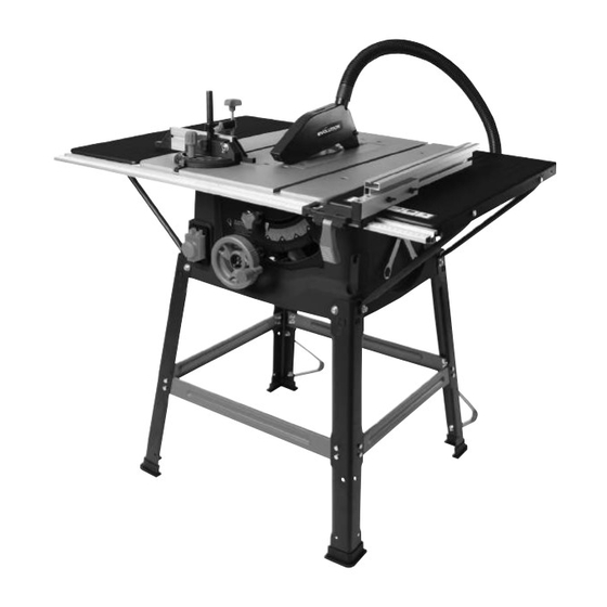
www.evolutionpowertools.com MACHINE OVERVIEW 1. ON/OFF SWITCH 7. RIP FENCE SCALE MAGNIFIER 2. RIVING KNIFE 8. RIP FENCE LOCKING HANDLE 3. BLADE GUARD 9. PUSH STICK 4. BLADE 10. RIP FENCE 5. BEVEL LOCKING KNOB 11. REAR CANTILEVER BRACES 6. RISE AND FALL/BEVEL ADJUSTMENT 12. -
Page 13: What's In The Box
www.evolutionpowertools.com WHAT’S IN THE BOX A. BLACK CORNER LEGS (STAMPED A) x 4 K. MITRE GAUGE B. CROSS-BRACES (STAMPED B) L. FENCE RAIL 2 pieces C. CROSS-BRACES (STAMPED C) M. FENCE RAIL JOINING TONGUE D. REAR CANTILEVER BRACES N. HEX HEADED SCREW x 28 E. -
Page 14: Assembly
www.evolutionpowertools.com ASSEMBLY Note: This process can be considerably aided by studying the images of an assembled machine as found on the machine overview page. THE STAND Four corner legs (A) (stamped A) and four cross-braces (B+C) comprise the main stand components. Four cross-braces are supplied (Fig 1). -
Page 15: Attaching The Table Extensions
www.evolutionpowertools.com • Attach the side cross-braces (C) to the corner legs (Fig. 5) in the same manner as the front and rear cross-braces were attached. Note: The machine can now be lifted from the work-surface/workbench. WARNING: This machine is heavy. Enlist competent help when lifting this machine from the workbench. -
Page 16: The Fence Rail
www.evolutionpowertools.com Use a straight edge or similar placed across the table and the extension panel to check the alignment. The extension panels should be exactly level with and flush to the main table of the machine. Note: The support struts and the extension panels are provided with elongated slotted holes. -
Page 17: Checking/Adjusting The Rip Fence
www.evolutionpowertools.com • Gently move the fence rail to the right or left until the ‘0’ position on the scale coincides with the datum line in the magnifier. (Fig. 13) • Check, and when satisfied that calibration has been achieved, tighten the seven fence rail nuts (S) securely. •... -
Page 18: Top Blade Guard
www.evolutionpowertools.com The pillar of the anti-bounce device fits into the socket in the mitre gauge base, and is held in place by a thumb screw. (Fig 17) TOP BLADE GUARD The top blade guard (H) (Fig. 18) (sometimes referred to as a crown guard) must always be fitted to the machines riving knife. -
Page 19: Operation
(Fig. 22) Note: The ‘free’ port of the 2 way connector can be used to attach a workshop dust extraction machine to this Evolution Fig. 21 machine. If such a machine is connected to this Table Saw follow the Instructions provided by the supplier/manufacturer of the dust extraction equipment. -
Page 20: Tilting The Blade
www.evolutionpowertools.com When the hand-wheel is pushed in against its bias spring a cog engages with a curved toothed rack incorporated into the machines main body. This allows the hand-wheel to be used to adjust the tilt/bevel angle of the blade To raise or lower the blade: •... -
Page 21: Rip Fence Guide
www.evolutionpowertools.com Forwards and backwards adjustment of the rip fence faceplate (Fig. 28) is possible. Loosen the two wing nuts and slide the aluminium faceplate to the desired position. Tighten the wing nuts securely. Note: We recommend that normally the rip fence faceplate be adjusted so that the rear of the faceplate guide is ‘in line’... -
Page 22: Anti-Bounce Device
www.evolutionpowertools.com Turn the vertical handle counter-clockwise to unlock the mitre gauge, and adjust to the required angle. Turn the handle clockwise to lock the mitre gauge at the chosen angle. (Fig. 32) Note: The extruded aluminium faceplate of the mitre gauge should be adjusted so that it passes close to, but does not touch the blade or blade guard. -
Page 23: Cross-Cutting
www.evolutionpowertools.com CROSS-CUTTING Set the mitre gauge to 0˚ and tighten using the vertical handle. Position in the desired ‘T’ slot and adjust the mitre face plate as previously described. Index and hold the material to be cut against the mitre gauge faceplate (Fig.36). Switch on the saw and allow the blade to reach full operating speed before making the cut. -
Page 24: Rip Cutting
www.evolutionpowertools.com To set the rip fence for repetitive cross-cutting: • Set the rip fence at the required distance from the saw blade. • Adjust and align the back of the rip fence faceplate with the front of the saw blade. (Fig. 39) This setting will afford clearance for the material as it passes through the saw blade. -
Page 25: Bevel Ripping
www.evolutionpowertools.com saw blade. The operators right hand will be close to the rip fence on the RH side of the sawblade. WARNING: The operators hands should never be in line with the blade. BEVEL RIPPING Bevel ripping is cutting along the length of a work-piece with the saw blade tilted at an angle. -
Page 26: Cleaning
Note: Use only a genuine Evolution riving knife, as this is a dedicated component for this machine. Non genuine parts could be dangerous. If in any doubt, please contact the helpline. - Page 27 In accordance with EN ISO 17050-1:2004 The manufacturer of the product covered by this Declaration is: Evolution Power Tools, Venture One, Longacre Close, Holbrook Industrial Estate, Sheffield, S20 3FR. The manufacturer hereby declares that the machine as detailed in this declaration fulfils all the relevant provisions of the Machinery Directive and other appropriate directives as detailed below.
-
Page 28: Declaration Of
Total Tools (Importing) Pty Ltd Evolution Power Tools SAS 20 Thackray Road 61 Avenue Lafontaine Port Melbourne 33560, Carbon-Blanc Vic 3207 Bordeaux T: 03 9261 1900 T: +33 (0)5 57 30 61 89 Evolution Power Tools Ltd Evolution Power Tools LLC...
Need help?
Do you have a question about the R255MTS and is the answer not in the manual?
Questions and answers