SORG Jump alpha Service Record
Hide thumbs
Also See for Jump alpha:
- Service record (36 pages) ,
- Instructions for use manual (48 pages)
Table of Contents
Advertisement
Quick Links
Advertisement
Table of Contents

Related Manuals for SORG Jump alpha


Summary of Contents for SORG Jump alpha
- Page 1 service record Service Record Jump alpha...
-
Page 2: Imprint
We are a member of rehaKIND e.V. International association child and adolescent rehabilitation COPYRIGHT © by SORG Rollstuhltechnik GmbH + Co. KG Benzstraße 3-5, 68794 Oberhausen-Rheinhausen. All texts and pictures in this user manual underlie the international copyright protection and are not allowed to be published without our consent –... -
Page 3: Table Of Contents
service record IMPRINT 2.6.2 Skirt guard on the side guard REVISION STATUS 2.6.3 Armrest on the side guard TECHNICAL STATUS rehaKIND ASSEMBLY GROUP BRAKES COPYRIGHT 2.7.1 Standard wheel lock CERTIFICATION 2.7.2 Lockable wheel lock Inhaltsverzeichnis 2.7.3 Cable brake WHEELCHAIR OVERVIEW 2.7.4 Drum brake ASSEMBLY GROUP ANTI TIPPER/TIPPING LEVER... -
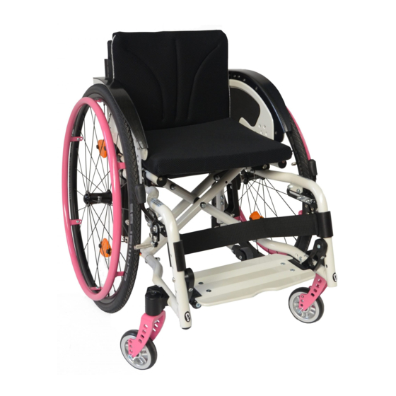
Page 4: Wheelchair Overview
Jump alpha WHEELCHAIR OVERVIEW push handles back side guard skirt guard seat brake lever brake bolt frame foot plate (continuous) 10. caster forkl 11. caster 12. driving wheel 13. hand rim 14. quick release axle 2 3 4 5 push handles... -
Page 5: Preamble
For liability reasons we have to ask you to check ments according to 93/42/EWG, 2007/47/EWG and the wheelchair IMMEDIATELY after receiving it and EN12183:2009. SORG Rollstuhltechnik is also certi- IN THE PRESENCE of the deliverer (forwarding com- fied according to the quality management system ISO pany) for possible damages that may have occurred 9001. -
Page 6: Documentation
Jump alpha ADJUSTMENTS ON THE WHEELCHAIR INFORMATION GENERAL INFORMATION Proceed according to the maintenance plan in the user manual. ATTENTION: DANGER OF BRUISING When operating the adjustable parts (back rest, side DOCUMENTATION guard, leg support, wheel lock, positioning aids etc.) as well as fixation and reparation work, there is an �... -
Page 7: Assembly Group Wheels
service record ASSEMBLY GROUP WHEELS 2.3.1 Centre of gravity(wheel base, perforated plate) From the configuration of the rear wheels and casters, the focal point, the wobbliness of the wheelchair, the seat height in front and back and the seat angle can be set. (1) To set the centre of gravity •... -
Page 8: Seat Height In Back, Seat Slant
Jump alpha 2.3.3 Seat height in back, seat slant 2.3.6 Removable rear wheels ATTENTION ATTENTION No person can be sitting in the wheelchair while mount- After each change made on the rear wheels the function- ing/demounting the wheels. It must be supported and tip... -
Page 9: Camber
service record 2.3.7 Camber With the camber you influence: • the side tilt stability, • the shoulder rear wheel position and • the track width of the wheelchair. INFORMATION (1) To avoid the so called “eraser effect” we general- ly mount the fitting track balance ex-works (A). With a change of the camber afterwards, the track balance adapter (A) must be replaced by one that fits (spare part). -
Page 10: Rear Wheel Track Balance
Jump alpha 2.3.8 Rear wheel track balance If you have to change the camber and/or the seat slant you must, in order to avoid the so called “eraser effect”, mount appropriate wedge plates for the track balance. To change/set the wedge plate;... -
Page 11: Assembly Group Seat
service record ASSEMBLY GROUP SEAT 2.4.1 Changing the seat cover (1) To change the seat cover, remove both screws (A) on the bottom of the seat tube. Pull the seat cover (B) forward, out of the tube (C). Thread the new seat cover on to the cover rods. -
Page 12: Changing The Seat Width
Jump alpha 2.4.5 Changing the seat width The seat width of a Jump can be changed 1 cm on each side with spacers between frame and side guards. The parts required for this are sent in a pouch in the utensil bag under the seat cover (6 round spacers plus the necessary screws). -
Page 13: Assembly Group Leg Supports
service record ASSEMBLY GROUP LEG SUPPORTS � INDICATION 2.5.1 Term definition The leg supports are ideally fixated (A) when the whole thigh is evenly resting on the seat cushion to about 2 fin- The leg support is the part of the wheelchair which sup- ger widths in front of the back of the knee, while the leg ports your legs. -
Page 14: Leg Support Inner Attachment
Jump alpha 2.5.2 Leg support inner attachment 2.5.3 Leg support outer attachment Setting the lower leg length Setting the lower leg length (1) Remove the screws (A) on the outer side of the frame on (3) Remove the screws (A) on the outer side of the frame on both sides. -
Page 15: Continuous Foot Plate, Folds Up Sideways
service record 2.5.4 Continuous foot plate, folds up sideways � INDICATION The setting of the depth and the angle, as well as the fine adjustments of the locking claw and the respective foot plate occurs as already described. 2.5.5 Divided foot plate, folds up sideways ATTENTION The divided foot plate is NOT suitable for users with tone dysregulation. -
Page 16: Side Guards
Jump alpha SIDE GUARDS 2.6.2 Skirt guard on the side guard 2.6.1 Setting side guards (3) The skirt guard is placed on the side guard and should (1) The inner space between wheel and side guard should cover the rear wheel to the outer side of the wheel. -
Page 17: Assembly Group Brakes
service record ASSEMBLY GROUP BRAKES wheel lock/service brake (1+2) Every wheelchair is equipped with two wheel locks. They consist of brake pressing bolt (A), brake lever (B) (if necessary, also with an extension) and adjustment screws (C). ATTENTION WHEEL LOCKS ONLY SERVE THE PURPOSE OF PUTTING THE WHEELS IN A RESTING POSITION. -
Page 18: Standard Wheel Lock
Jump alpha 2.7.1 Standard wheel lock (1) Check the air pressure in the driving wheels first (re- quired details on the tire cover). To adjust the brake loosen both screws (A) on both sides, place brake in the appropri- ate position and retighten the screws (A) 2.7.2 Lockable wheel lock... -
Page 19: Drum Brake
service record 2.7.4 Drum brake The drum brake, unlike the wheel lock, is also suitable as a driving brake. (1) The adjustment of the drum brake occurs through a screw on the bottom end of the brake cable (A). By turning the screw counter clockwise the brake cable can be tight- ened. -
Page 20: Assembly Group Anti Tipper/Tipping Lever
Jump alpha ASSEMBLY GROUP ANTI-TIPPER/TIP- PING LEVER (1) The anti-tipper consists of 4 parts:: • (A) anti-tipper holder, • (B) foot lever, • (C) anti-tipper wheel with holder, • (D) anti-tipper bail which can be pulled down and turned 180° (partly sticking in the anti-tipper hold- er). -
Page 21: Assembly Group Back
service record ASSEMBLY GROUP BACK 2.9.1 Adjustable back cover The back belts can be adjusted which enables an individual molding of the back. For example, if the upper belts on the back are loosened, then a molding form of the back follows and allows more torso stabilization from the side for the wheelchair user. -
Page 22: Adjusting The Back Angle
Jump alpha 2.9.4 Adjusting the back angle 2.9.6 Extension on standard backs (1) The tilting angle of the back rest can be adjusted or fold- (4) Remove the screws (A) on the frame of the back tubes ed down in steps by pulling the locking bolts (A) on the ring on both sides. -
Page 23: Assembly Group Push Aids
service record 2.10. ASSEMBLY GROUP PUSH AIDS 2.10.1 Standard push handles ATTENTION The push handles have black caps made of synthetic ma- terial. Under adverse circumstances the caps can loosen. For example from heat, if moisture gets in the caps or by extreme strain. -
Page 24: Assembly Group Truss Pads
Jump alpha 2.11 ASSEMBLY GROUP TRUSS PADS 2.11.1 Classification (1) The truss pads consist of the following parts: • (A) connection (C-bar) • (B) truss pad cushion • (C) truss pad holder • (D) locking joint 2.11.2 Vertical setting (2) The vertical setting of the truss pads occurs on the one hand by moving the locking joint (A). -
Page 25: Assembly Group Outdoor Front End
service record 2.12 ASSEMBLY GROUP OUTDOOR FRONT (1) The push aid for outside can be extended in length and in width. Each connection (A) is fixated with two Tuflok screws each. There are threads cut in to the inner tube, in which the Tuflok screws are screwed in. -
Page 26: Repairs And Maintenance
Jump alpha 3 REPAIRS AND MAINTENANCE TECHNICAL DATA Misprints and technical changes reserved. � INDICATION For safety reasons, when using the wheelchair regularly a Labelling M e a s u r e - Comments yearly inspection according to the following maintenance ments checklist is necessary. -
Page 27: Type Label
CE-sign back height seat depth max. load type number capacity DECLARATION OF CONFORMITY SORG Rollstuhltechnik GmbH & Co.KG Benzstraße 3-5 D-68794 Oberhausen-Rheinhausen Tel.: +49 7254 9279.0 Fax: +49 7254 9279.10 e-mail: info@sorgrollstuhltechnik.de Web: www.sorgrollstuhltechnik.de declares with this in sole responsibility, that the following aid Jump alpha Type Nr.: 485... - Page 28 Jump alpha Your specialized retailer company stamp SORG Rollstuhltechnik GmbH + Co. KG Benzstraße 3-5 D-68794 Oberhausen-Rheinhn. Tel +49 7254 9279-0 Fax +49 7254 9279-10 info@sorgrollstuhltechnik.de www.sorgrollstuhltechnik.de Technical changes and misprints reserved.
Need help?
Do you have a question about the Jump alpha and is the answer not in the manual?
Questions and answers