Table of Contents
Advertisement
Quick Links
Total solder points: 117
Difficulty level: beginner 1
2
3
ILLUSTRATED ASSEMBLY MANUAL
4
5
advanced
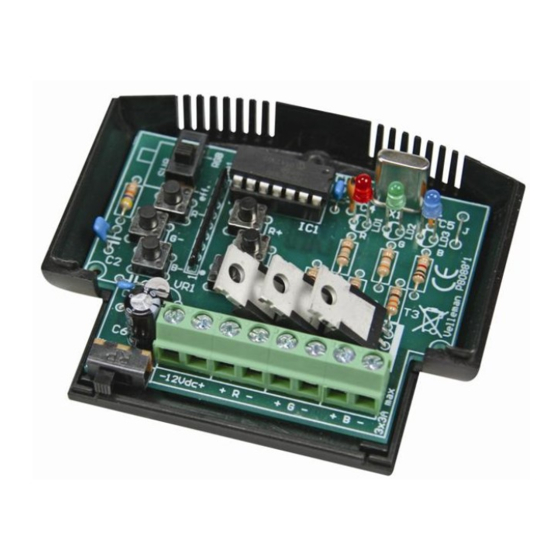
RGB Controller
K8088
Specifications
256 intensity levels/ch.
voltage output : same as input voltage
current limit possible (on-board resistor needed)
LED PWM freq. : 82Hz
power supply : 10 - 15Vdc / 9A max.
dimensions : approx 80x70x23mm
H8088IP-1
Advertisement
Table of Contents

Related Manuals for Velleman K8088


Summary of Contents for Velleman K8088
- Page 1 Total solder points: 117 Difficulty level: beginner 1 advanced RGB Controller K8088 Specifications 256 intensity levels/ch. voltage output : same as input voltage current limit possible (on-board resistor needed) LED PWM freq. : 82Hz power supply : 10 - 15Vdc / 9A max.
-
Page 2: Features And Specifications
Features & Specifications Ideal for use with flexible LED light lights strips, ex. RGB Led. (ordernr. LDB1-HS3027AC) Features: suited for both incandescent bulbs and LEDs up-down level adjust for each output hard transition effects : runnning light, Strobo, Colour loops, etc... smooth fade effects : colour change, flame effect, random colours, slow off etc... -
Page 3: Assembly Hints
Assembly hints 1. Assembly (Skipping this can lead to troubles ! ) Ok, so we have your attention. These hints will help you to make this project successful. Read them carefully. 1.1 Make sure you have the right tools: • A good quality soldering iron (25-40W) with a small tip. - Page 4 Assembly hints 1.3 Soldering Hints : 1- Mount the component against the PCB surface and carefully solder the leads 2- Make sure the solder joints are cone-shaped and shiny 3- Trim excess leads as close as possible to the solder joint REMOVE THEM FROM THE TAPE ONE AT A TIME ! DO NOT BLINDLY FOLLOW THE ORDER OF THE COMPONENTS ONTO THE TAPE.
-
Page 5: Push Buttons
Construction 1. Jumper wire 3. Diode. Watch the polarity! 6. Capacitors. C... D1 : 1N4007 CATHODE D... C1 : 100nF (104) C2 : 100nF (104) 4. Resistor array C3 : 100nF (104) 2. Resistors C4 : 15pF (15) C5 : 15pF (15) R... -
Page 6: Terminal Blocks
construction 8. Switches 9. Voltage regulator 11. Electrolytic Capacitor. Watch the polarity ! SW1 : ON / OFF VR... SW1. C... VR1 : UA78L05 C6 : 100µF / 25V SW8 : RGB / effect -mode 10. Terminal blocks 12. Crystal X... - Page 7 Construction 12. LEDs. Watch the polarity! 13. Transistors IMPORTANT COLOR= 2...5 Apply an extra layer of solder on all copper 14mm LD... 17mm 14mm PCB tracks. CATHODE LD1 : 3mm Red "R" TR1 : BUK9535-55 LD2 : 3mm Green "G" TR2 : BUK9535-55 LD3 : 3mm Blue "B"...
- Page 8 Description Description 1) On/off switch 2) Mode switch. Select between ‘RGB’- and ‘Effect’-mode ‘RGB’-mode: Red, Green and Blue output levels can be individually adjusted by means of the up/down buttons ‘Effect’-mode: Allows to choose between 11 built-in effects 3) Output indicator leds. 4) Power supply connector.
- Page 9 LED-strip with common anode (+) : Connect the common anode to the (+) of the 12VDC power supply. Connect the cathode (-) of each colour to the (-) of R,G or B on the K8088. Place a wire jumper for R4, R5 and R6.
- Page 10 Connection LED: LEDs require a series resistor (R4, R5 or R6) Determine led voltage drop (Check manufacturer datasheet). Rule of thumb: red: 1.7V, green: 2V, blue: 3..4V). Next, check required LED current. Example: 12VDC Red LED, 1.7V drop, required current: 20mA Resistor calculation: (12V-1.7V) / 0.020 = 515 ohm (choose nearest value, e.g.
- Page 11 RGB-mode (mode switch into position ‘RGB’) This mode allows you to compose a desired colour by adjusting the level of each channel. RED-level down RED-level up GREEN-level down GREEN-level up BLUE-level down BLUE-level up Memory: Once you have composed a colour, you can store it in memory by flipping the mode switch to ‘eff'. Next time, when you turn on the controller with the slide switch set to ‘RGB’, it will revert to the colour you’ve composed.
- Page 12 Effect-mode (mode switch SW8 in position ‘eff’) This mode allows you to select one of the 11 available effects, using the buttons (8) and (9) Effect # Description Select a static colour by means of buttons (12) and (13). Static colours Colours: Red - Green - Red/Green - Blue - Red/Blue - Green/Blue - Red/Green/Blue Sequenced colours Same as above, but automatically sequenced...
- Page 13 Mounting order overview Mounting order overview Mount the PCB onto the lower part of the housing, see figure. Place the front and rear sticker on the housing.
-
Page 14: Schematic Diagram
Schematic diagram Schematic diagram. +12V +12V 1N 4007 SK 1 VR 1 UA78L05 SCR EW02 100n SK 2 100µ/25V GN D IRF 540 BUK9535-55 100n PIC 16F630-I/P GN D +12V BLUE RA 5/T1CKI/OSC1/C LKIN RC 3 20M Hz RA 4/T1G/OSC 2/CLKOU T RC 4 SK 3 RC 5... - Page 16 Modifications and typographical errors reserved - © Velleman nv. H8088IP'1 - 2008 (rev.1) 5 4 1 0 3 2 9 3 8 5 6 0 6...
Need help?
Do you have a question about the K8088 and is the answer not in the manual?
Questions and answers