
Related Manuals for Velleman K2639


Summary of Contents for Velleman K2639
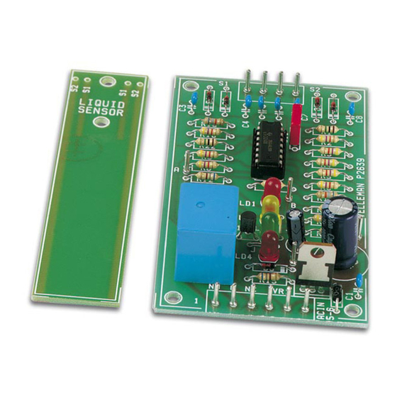
- Page 1 Total solder points: 129 Difficulty level: beginner 1 advanced LIQUID LEVEL CONTROLLER K2639 ILLUSTRATED ASSEMBLY MANUAL H2639IP-1...
-
Page 2: Specifications
Introduction & Specifications Did you forget to turn off the tap? Is the washing machine leaking? Will the aquarium level fall too low? Has the rain water tank overflowed? Do you have water in the cellar? Just a minor mishap, or a disaster! You can avoid all this by installing the liquid level controller in the right way and in the right place. -
Page 3: Assembly Hints
Assembly hints 1. Assembly (Skipping this can lead to troubles ! ) Ok, so we have your attention. These hints will help you to make this project successful. Read them carefully. 1.1 Make sure you have the right tools: • A good quality soldering iron (25-40W) with a small tip. - Page 4 3- Trim excess leads as close as possible to the solder joint REMOVE THEM FROM THE TAPE ONE AT A TIME ! AXIAL COMPONENTS ARE TAPED IN THE CORRECT MOUNTING SEQUENCE ! You will find the colour code for the resistances and the LEDs on our website: http://www.velleman.be/common/service.aspx...
- Page 5 Construction R8 : 47K (4 - 7 - 3 - B) C7 : 100nF (104) 1. Jumpers R9 : 47K (4 - 7 - 3 - B) C8 : 100nF (104) R10 : 47K (4 - 7 - 3 - B) J : 2x R11 : 47K (4 - 7 - 3 - B)
- Page 6 Construction 8. Capacitor 10. Electrolytic capacitor. 13. Relay Watch the polarity ! C9 : 10µ F / 25V C... RY... C11 : 22nF 9. PCB pins RY1 : VR15M121C 12V / 15A 11. Voltage regulator 14. IC mounting VR1 : UA7812 Fit four terminal pins between marks S1 and VR...
- Page 7 Testing 15. Testing Inspect the completed board thoroughly before connecting a power supply. When applying a DC voltage (16 to 18V/100 mA) : The positive input should go to the pin nearest “AC IN” , the negative input to the second pin (Fig 1.0). ACin ACin Fig 1.0...
- Page 8 Testing With power on, LD3 (LOW LEVEL) should illuminate, showing that everything works. Put a link across low-level sensor S2, and LD2 should illuminate. Fig 3.0 Add another link across high-level sensor S1, and LD1 and LD4 should both illuminate. Fig 3.1 Remove the link across input sensor S1, now LD2 should illuminate together with LD4 (relay on).
- Page 9 Applications 16. Applications For application as controller/indicator and alarm, 1 or 2 sensors must be connected. A sensor consists of 2 separated electric conductors : 2 metal strips on a PCB or a jack plug etc. There are 2 sensors on the sensor PCB : S1 (HIGH LEVEL) and S2 (LOW LEVEL).
- Page 10 Applications A dry sensor behaves like an electric isolator. When the sensor is wet the resistance drops to some Kilo-Ohms maximum. The electrical resistance of a sensor depends on the conductivity of the liquid, spacing between the electrodes, and the wet areas of the electrodes. The specific conductivity of some liquids is so high that this controller can’...
- Page 11 Applications Working : With both sensors dry, LD3 illuminates (LOW LEVEL), fig 6.0 When sensor S2 is wet, LD2 illuminates (MEDIUM LEVEL), fig 6.1 When the liquid level rises and S1 also becomes wet, LD1 (HIGH LEVEL) and LD4 (relay “ on” ) illuminate, fig 6.2 If the level then falls and only sensor S2 remains wet, LD2 and LD4 illuminate, fig 6.3 If the level keeps falling and sensor S2 also becomes dry, only LD3 illuminates, and the relay is switched off, fig 6.0 To Main PCB...
- Page 12 Applications NOTE : the relay is switched on when the level reaches S1 (HIGH LEVEL) and is then switched off when the level falls under S2 (LOW LEVEL) ATTENTION : The relay contacts are rated at 3 Amps max. ALARM Link the pins of sensor S1 to the pins of sensor S2 as follows : 1) link the pin near C5 to the pin near C6 2) link the pin near C4 to the pin near C7...
- Page 13 Applications ALARM WITH HOLD MEMORY I. Alarm when the sensor detects liquid : Mount liquid sensor S1 and connect a NC pushbutton with the connection pins of sensor S2. As soon as the sensor detects liquid, the relay receives power (LED LD4 starts burning) and remains powered, even when the sensor returns to a dry state.
- Page 14 Schematic diagram 17. Schematic diagram.
- Page 15 18. PCB...
- Page 16 VELLEMAN Components NV Legen Heirweg 33 9890 Gavere Belgium Europe www.velleman.be www.velleman-kit.com Modifications and typographical errors reserved © Velleman Components nv. H2639IP - 2004 - ED1 (rev.1.0) 5 4 1 0 3 2 9 3 2 3 5 4 7...
Need help?
Do you have a question about the K2639 and is the answer not in the manual?
Questions and answers