
Related Manuals for Enertech Bentone BG400


Summary of Contents for Enertech Bentone BG400
- Page 1 178 024 73-3 2016-12-06 Providing sustainable energy solutions worldwide Installation- and maintenance instruction BG400...
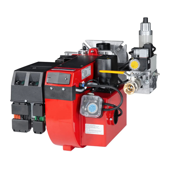
- Page 3 DESCRIPTION Components 8. Air dampe 16. Motor 1. Cover,inspection glass 9. Air intake 17. Ignition electrode 2. Air pressure switch 10. Gas pressure switch 18. Transformer 3. Air adjustment 11. Ball valve 19. Ionization electrode 4. Inner assembly adjustment 12. Control box 20.
-
Page 4: Technical Data
TECHNICAL DATA Type designation BG 400 Dimensions Length of burner tube Measure A Standard The above dimensions are max. measurements. Depending on the compo- nents used, the measurements may vary. Output range Type Capacity Gas volume at a min. Gas volume at a max Max. - Page 5 TECHNICAL DATA Dimensions of fl ange ø140 172 215 30 07-01...
- Page 6 SKELETON DIAGRAMS, 1-STAGE BURNER Incorporated in the MultiBloc Pos. 5b, 7: Components not required 1. Ball valve 6a. Main valve 2. Filter 6b. Safety valve according to EN 676. 3. Governor 7. Valve proving system 4. Pressure gauge with shut-off cock 9.
-
Page 7: Mounting On The Boiler
MOUNTING ON THE BOILER Remove the combustion unit from the Removal of fan house unit from Installation example burner. Fit the enclosed fl ange and burner. Connect the gas to the burner by gasket to the boiler. If new fi xing holes Loosen the screws. -
Page 8: Electric Equipment
ELECTRIC EQUIPMENT Gas burner control: LME11/LME21 Wiring diagram If there is no plug-in contact (X2) on the boiler, connect to the contact enclosed. In case the twin thermostat is in series on incoming phase L1, a loop between the terminals T1 and T2 is necessary. - Page 9 ELECTRIC EQUIPMENT Control diagnosis under fault conditions and lockout indication Gas burner control: LME..Colour codes Colour code table for multi-coloured signal lamps (Light diodes) Status Colour codes Colours ○………………… Waiting time «tw», other waiting times Ignition phase, ignition checked •○...
- Page 10 ELECTRIC EQUIPMENT Control diagnosis under fault conditions and lockout indication Gas burner control: LME... Alarm control table Red fl ashing code Possible causes on signal lamp (LED) • No fl ame at End of «TSA» Flashing 2 x – Defective or obscured fl ame monitor ••...
- Page 11 MEASURES AND CHECKS BEFORE START-UP, 1-STAGE BURNER General rules Leakage control Care should be taken by the installer (0,5-2,5 sec. dependent on the design When making a leakage control of the to ensure that no electrical cables or of the gas control). The gas valve is gas supply system the solenoid valve energized and opens and fl...
- Page 12 MEASURES AND CHECKS BEFORE START-UP INNER ASSEMBLY Town gas INNER ASSEMBLY Natural gas, LPG Natural gas INNER ASSEMBLY Biogas (UV-detector) 172 205 78 07-01...
- Page 13 DETERMINATION OF GAS VOLUME FOR THE INSTALLATION Specifi cations on natural gas, town Net calorifi c value gas and bio gas vary. For more exact Gas quality kWh/Nm kJ/Nm kcal/Nm information please contact the gas Natural gas 10,3 37 144 8 865 distributor.
- Page 14 ADJUSTMENT OF MULTI-BLOC, MB-DLE 405-407 Flow adjustment Loosen the fi xing screw a. Turn the hydraulic device b: to the right = the gas fl ow is reduced to the left = the gas fl ow is increased Do not forget to tighten the fi xing screw again.
-
Page 15: General Instructions
GENERAL INSTRUCTIONS Adjustment of burner A general rule is that the lower capacity Service the smaller the opening between The burner is from the factory pre-set Service should only be carried out by qualifi ed personnel. Replacement brake plate and combustion device. to an average value that must then be adjusted to the boiler in question. - Page 16 GENERAL INSTRUCTIONS, 1-STAGE BURNER Air adjustment Loosen the stop screw and turn the knob along the scale to the desired position and tighten the screw. Check the air adjustment by making a fl ue gas analysis. Adjustment of brake plate Loosen the screw on the adjust- ment device.
-
Page 17: General Instruction
GENERAL INSTRUCTION Flame monitoring and measure- Adjustemnt of max. gas pressure Adjustment of air pressure switch ment of ionisation current switch The air presure switch should stop the The burner is monitored according The burner is equipped with a max. burner if the air volume is reduced. - Page 18 FINAL TEST OF THE INSTALLATION – Make repeated start attempts to Fault location, functional troubles ensure that the adjustments Trouble free operation is dependent on three factors: electricity, gas and air function. supply. Should there be any changes – Close the ball valve during in the ratio between these three factors operation to check that the gas there is a risk of break downs.
-
Page 19: Gas Burner
Fault location guide Gas burner The basis for a trouble free operation can only be ensured by the correct combined effect of the three factors: electricity, gas fl ow and combustion air. Should any of these factors change, troubles may arise. t has been proved that many troubles have rather simple causes. - Page 20 Cause Remedy No electrical connection through the air pressure switch Test the adjustment and the function of the air pres-sure switch. The starting load is not correctly adjusted Reduce or increase the gas supply, reduce the quanti ty of air. Gas relay defective Replace Air pressure switch incorrectly adjusted or defective...
- Page 21 Cause Remedy The burner is operating correctly but locking out now and then The ionisation current is too low Check. Must be at least 4 µ A according to the relay manufacturer but should be 8-20 µ A. The UV-cell is in a wrong position Adjust Voltage drop at certain times Must not drop more than 15% of the rated...
- Page 22 Cause Remedy The burner is operating correctly but locking out now and then The ionisation current is too low Check. Must be at least 4 µ A according to the relay manufacturer but should be 8-20 µ A. The UV-cell is in a wrong position Adjust Voltage drop at certain times Must not drop more than 15% of the rated...
-
Page 23: Declaration Of Conformity
CE-0085 AU 0156 BG450 Enertech AB declares that the above-mentioned products Enertech AB erklärt hiemit, dass oben genannten Produkte mit comply with the following standards or other normative den folgenden Normen oder anderen normativen Dokumenten documents and meet applicable sections of the EU directive. -
Page 25: General Instructions For Gasburners
GENERAL INSTRUCTIONS FOR GASBURNERS Installation Follow standards and instructions applicable to the Check that the input pressure of the gas is correct installation of gas burners Check that the dampers of the boiler are open Ensure that the electric installation is made in Check that there is water in the system accordance with existing regulations Check that thermostats etc. - Page 26 SERVICE AND INSPECTION CARD Installation Boiler Name: Type: Effi ciency kW: Address: Burner Type: Effi ciency kW: Installed by: Date: Date gas/h Governor Flue gas Ionisa- Pressure Effi ciency temp tion current Fire room Chimney Measure- Before After °C µ A mbar mbar % ment...
- Page 32 Enertech AB. P.O Box 309, SE-341 26 Ljungby. www.bentone.se, www.bentone.com...
Need help?
Do you have a question about the Bentone BG400 and is the answer not in the manual?
Questions and answers