Advertisement
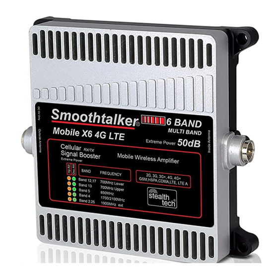
Mobile X6 4G LTE
Wireless Booster
Extreme Power
User Manual
Cellular
RX/TX
Signal Booster
Wireless Booster Extreme Power
2G, 3G, 3G+, 4G, 4G+
GSM,HSPA,CDMA,LTE, LTE A
Band 12,17
Band 13
Band 5
Band 4
Band 2,25
50dB 6 BAND
MULTI BAND
50dB
700MHz Lower
700MHz Upper
850MHz
1700/2100MHz
1900MHz ext
BMUX650
USA
stealth
12V DC CLA OR 12V DC
POWER SUPPLY
fused or 120V AC/DC
Weight
6 BAND
MULTI BAND
50dB
tech
®
1.2 lb
Advertisement
Table of Contents

Related Manuals for SmoothTalker Mobile X6 4G LTE


Summary of Contents for SmoothTalker Mobile X6 4G LTE
- Page 1 6 BAND Mobile X6 4G LTE MULTI BAND Wireless Booster 50dB Extreme Power BMUX650 User Manual Cellular RX/TX 50dB 6 BAND Signal Booster MULTI BAND 50dB Wireless Booster Extreme Power 2G, 3G, 3G+, 4G, 4G+ GSM,HSPA,CDMA,LTE, LTE A Band 12,17...
- Page 2 Contents Inside antenna Cellular Booster Optional outside antenna SRP1X SEM2MX SEM11MX SEM14MX Optional Power Types 120 volt AC/DC 12 volt socket plug type 12 volt install type NOTE: Only one of the outside antennas is included in this kit (check model) All kits include necessary brackets and co-axial cables for assembly.
- Page 3 Installation 1) Connect the outside antenna to the side of the booster marked as “outside antenna” Connect the inside antenna to the side of the booster marked as “inside antenna” 2) Placement Place the outside antenna in the middle of the vehicle roof. If the vehicle has a sunroof please place the antenna on the roof towards the back window.
- Page 4 Understanding the LED Indicators RX High Power Attenuation Oscillation Attenuation Band Frequency Band 12, 17 700MHz Lower Band 13 700MHz Upper Band 5 850MHz Band 4 1700/2100MHz Band 2, 25 1900MHz ext Green LED Orange LED The “LEDS” on the face of the booster indicate operating gain state. In any given frequency band.
- Page 5 LED Lights Explanation and Troubleshooting Each flash indicates 3dB of gain reduction also known as gain attenuation. For example: three flashes equals 9dB of attenuation. Green LED indicates loop oscillation status. When flashing it means reduction of gain. To improve you need to spread the distance between the inside and outside antennas.
- Page 6 Approved Equipment List FCC requirements prohibit the use of unauthorized Antennas, Cables, and/or Coupling devices. You MUST operate this device with approved antennas and cables as specified by the manufacturer. Antennas MUST be installed at least 8 inches from any person. You MUST cease operating this device immediately if requested by the FCC or a licensed wireless service provider.
- Page 7 NPS and other compliance/safeguard features can not be field reconfigured, disabled or removed. This booster is not user programmable, does not need fine tuning or adjustment, does not require professional installation. Rely on premium rv electronics by Smoothtalker if you’re looking for quality and efficiency.
Need help?
Do you have a question about the Mobile X6 4G LTE and is the answer not in the manual?
Questions and answers