Table of Contents
Advertisement
Advertisement
Table of Contents

Related Manuals for WÄRTSILÄ 46DF


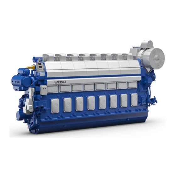
Summary of Contents for WÄRTSILÄ 46DF
- Page 1 Wärtsilä 46DF PRODUCT GUIDE...
- Page 2 © Copyright by WÄRTSILÄ FINLAND Oy COPYRIGHT © 2019 by WÄRTSILÄ FINLAND Oy All rights reserved. No part of this booklet may be reproduced or copied in any form or by any means (electronic, mechanical, graphic, photocopying, recording, taping or other information retrieval systems) without the prior written permission of the copyright owner.
- Page 3 For contracted projects specific instructions for planning the installation are always delivered. Any data and information herein is subject to revision without notice. This 01/2019 issue replaces all previous issues of the Wärtsilä 46DF Project Guides. Issue Published...
- Page 4 This page intentionally left blank...
-
Page 5: Table Of Contents
Wärtsilä 46DF Product Guide Table of contents Table of contents 1. Main Data and Outputs ..........................1.1 Maximum continuous output ....................... 1.2 Output limitations in gas mode ......................1.3 Reference conditions ........................... 1.4 Operation in inclined position ......................1.5 Dimensions and weights ........................ - Page 6 Table of contents Wärtsilä 46DF Product Guide 8. Compressed Air System .......................... 8.1 Instrument air quality ..........................8.2 Internal compressed air system ......................8.3 External compressed air system ......................9. Cooling Water System ..........................9.1 Water quality ............................9.2 Internal cooling water system ......................
- Page 7 Wärtsilä 46DF Product Guide Table of contents 19. Transport Dimensions and Weights ..................... 19-1 19.1 Lifting of engines ..........................19-1 19.2 Engine components ........................... 19-2 20. Product Guide Attachments ........................20-1 21. ANNEX ..............................21-1 21.1 Unit conversion tables ........................
- Page 8 This page intentionally left blank...
-
Page 9: Main Data And Outputs
1. Main Data and Outputs Main Data and Outputs The Wärtsilä 46DF is a 4-stroke, non-reversible, turbocharged and inter-cooled dual fuel engine with direct injection of liquid fuel and indirect injection of gas fuel. The engine can be operated in gas mode or in diesel mode. -
Page 10: Output Limitations In Gas Mode
1. Main Data and Outputs Wärtsilä 46DF Product Guide Output limitations in gas mode 1.2.1 Output limitations due to methane number Fig 1-1 Output limitations due to methane number Calculation Formulas for different compression ratios CR 12.7:1 if MN ≥ 80 and tbax ≤ 45 → KKNOCK = 1 if MN <... - Page 11 Wärtsilä 46DF Product Guide 1. Main Data and Outputs NOTE 1) Gas fuel methane number refers to the gas quality at the engine inlet. This may differ from the average gas quality in LNG tank. 2) Compensating a low methane number gas by lowering the charge air receiver temperature below 45 °C is not allowed.
- Page 12 1. Main Data and Outputs Wärtsilä 46DF Product Guide 1.2.2 Output limitations due to gas feed pressure and lower heating value Fig 1-2 Derating of output for gas feed pressure and LHV MJ/Nm3 KGAS kPa a NOTE 1) Values given in m3 are valid at 0°C and 101.3 kPa.
-
Page 13: Reference Conditions
Wärtsilä 46DF Product Guide 1. Main Data and Outputs Reference conditions The output is available within a range of ambient conditions and coolant temperatures specified in the chapter Technical Data. The required fuel quality for maximum output is specified in the section Fuel characteristics. -
Page 14: Dimensions And Weights
1. Main Data and Outputs Wärtsilä 46DF Product Guide Dimensions and weights Fig 1-3 In-line engines (DAAR038987) Engine LE1* LE3* LE5* 6L46DF 8670 8953 6170 1520 3255 1430 7L46DF 9635 9773 6990 1520 3255 1430 8L46DF 10310 10593 7810 1520... - Page 15 Wärtsilä 46DF Product Guide 1. Main Data and Outputs Fig 1-4 V-engines (DAAR038992) LE1* LE3* LE5* Engine 11036 7600 1921 3670 1620 12V46DF* 10375 7600 2043 3670 1620 12V46DF 11425 8650 2043 3670 1620 14V46DF 12687 9700 2347 3860 1620...
- Page 16 This page intentionally left blank...
-
Page 17: Operating Ranges
Wärtsilä 46DF Product Guide 2. Operating Ranges Operating Ranges Engine operating range Running below nominal speed the load must be limited according to the diagrams in this chapter in order to maintain engine operating parameters within acceptable limits. Operation in the shaded area is permitted only temporarily during transients. Minimum speed is indicated in the diagram, but project specific limitations may apply. -
Page 18: Loading Capacity
2. Operating Ranges Wärtsilä 46DF Product Guide Fig 2-1 Operating field for CP Propeller, 1145 kW/cyl, 600 rpm Remarks: The maximum output may have to be reduced depending on gas properties and gas pressure. The permissible output will in such case be reduced with same percentage at all revolution speeds. - Page 19 Wärtsilä 46DF Product Guide 2. Operating Ranges Fast load changes must be avoided during transfer from diesel to gas mode. The “emergency” loading ramp in diesel mode can be used in critical situations, e.g. when recovering from a fault condition to regain sufficient propulsion and steering as fast as possible.
- Page 20 2. Operating Ranges Wärtsilä 46DF Product Guide Unloading: In normal operation the load should not be reduced from high load to low load (much) faster than the load is increased. Crash stop can be recognised with a large lever movement form ahead to astern within some seconds, which overrides normal load reduction.
- Page 21 Wärtsilä 46DF Product Guide 2. Operating Ranges Fig 2-4 Maximum permissible load step in gas mode Gas - Mode Instant Load Application Stepwise Load Reduction •Maximum load step according to figure above •Maximum load step according to figure above •Steady-state frequency band ≤ 1.5 % •Steady-state frequency band ≤...
-
Page 22: Operation At Low Load And Idling
2. Operating Ranges Wärtsilä 46DF Product Guide NOTE 1) In case instant load steps are applied on top of Successive loading (ramp), the minimum time between load steps is 45 s and the maximum load application rate between steps is 10% / 60 s. However the maximum loading limit may not be exceeded. - Page 23 Wärtsilä 46DF Product Guide 2. Operating Ranges ● Between 5% and 10% MCR Max continuous operation time: 15 min; Requirements before further operation at low load can be continues: above 20% load for 30 min or change to back-up fuel (trip to diesel is also included as an automatic back-up feature) ●...
-
Page 24: Low Air Temperature
2. Operating Ranges Wärtsilä 46DF Product Guide 2.3.1 Nominal Start-up time 2.3.1.1 For preheated engine Fig 2-5 Nominal start-up time NOTE Continuous prelubrication of the engine can be done when the engine is in stop mode if shorter start-up time is required. -
Page 25: Technical Data
Wärtsilä 46DF Product Guide 3. Technical Data Technical Data Introduction This chapter contains technical data of the engine (heat balance, flows, pressures etc.) for design of ancillary systems. Further design criteria for external equipment and system layouts are presented in the respective chapter. - Page 26 3. Technical Data Wärtsilä 46DF Product Guide CPP Variable CPP Constant DE Constant Speed Speed Speed Wärtsilä 6L46DF Diesel Diesel Diesel mode mode mode mode mode mode Cylinder output 1145 1145 1145 Engine speed BSEC total at at 75% load...
- Page 27 Wärtsilä 46DF Product Guide 3. Technical Data CPP Variable CPP Constant DE Constant Speed Speed Speed Wärtsilä 6L46DF Diesel Diesel Diesel mode mode mode mode mode mode Cylinder output 1145 1145 1145 Engine speed External Pilot fuel feed pump, 1 feeder per =(850...1500) x...
- Page 28 3. Technical Data Wärtsilä 46DF Product Guide CPP Variable CPP Constant DE Constant Speed Speed Speed Wärtsilä 6L46DF Diesel Diesel Diesel mode mode mode mode mode mode Cylinder output 1145 1145 1145 Engine speed Pressure drop in external system, max.
-
Page 29: Wärtsilä 7L46Df
Wärtsilä 46DF Product Guide 3. Technical Data Wärtsilä 7L46DF CPP Variable CPP Constant DE Constant Speed Speed Speed Wärtsilä 7L46DF Diesel Diesel Diesel mode mode mode mode mode mode Cylinder output 1145 1145 1145 Engine speed Engine output 8015 8015... - Page 30 3. Technical Data Wärtsilä 46DF Product Guide CPP Variable CPP Constant DE Constant Speed Speed Speed Wärtsilä 7L46DF Diesel Diesel Diesel mode mode mode mode mode mode Cylinder output 1145 1145 1145 Engine speed SFOC at 75% load - LFO g/kWh 189.1...
- Page 31 Wärtsilä 46DF Product Guide 3. Technical Data CPP Variable CPP Constant DE Constant Speed Speed Speed Wärtsilä 7L46DF Diesel Diesel Diesel mode mode mode mode mode mode Cylinder output 1145 1145 1145 Engine speed Oil flow through engine Priming pump capacity (50/60Hz) 45.0 / 45.0...
- Page 32 3. Technical Data Wärtsilä 46DF Product Guide Note 1 At ISO 15550 conditions (ambient air temperature 25°C) and 100% load. Flow tolerance 8%. Note 2 At ISO 15550 conditions (ambient air temperature 25°C). Flow tolerance 8% and temperature tolerance 15°C.
-
Page 33: Wärtsilä 8L46Df
Wärtsilä 46DF Product Guide 3. Technical Data Wärtsilä 8L46DF CPP Variable CPP Constant DE Constant Speed Speed Speed Wärtsilä 8L46DF Diesel Diesel Diesel mode mode mode mode mode mode Cylinder output 1145 1145 1145 Engine speed Engine output 9160 9160... - Page 34 3. Technical Data Wärtsilä 46DF Product Guide CPP Variable CPP Constant DE Constant Speed Speed Speed Wärtsilä 8L46DF Diesel Diesel Diesel mode mode mode mode mode mode Cylinder output 1145 1145 1145 Engine speed SFOC at 75% load - LFO g/kWh 189.1...
- Page 35 Wärtsilä 46DF Product Guide 3. Technical Data CPP Variable CPP Constant DE Constant Speed Speed Speed Wärtsilä 8L46DF Diesel Diesel Diesel mode mode mode mode mode mode Cylinder output 1145 1145 1145 Engine speed Oil flow through engine Priming pump capacity (50/60Hz) 45.0 / 45.0...
- Page 36 3. Technical Data Wärtsilä 46DF Product Guide Note 1 At ISO 15550 conditions (ambient air temperature 25°C) and 100% load. Flow tolerance 8%. Note 2 At ISO 15550 conditions (ambient air temperature 25°C). Flow tolerance 8% and temperature tolerance 15°C.
-
Page 37: Wärtsilä 9L46Df
Wärtsilä 46DF Product Guide 3. Technical Data Wärtsilä 9L46DF CPP Variable CPP Constant DE Constant Speed Speed Speed Wärtsilä 9L46DF Diesel Diesel Diesel mode mode mode mode mode mode Cylinder output 1145 1145 1145 Engine speed Engine output 10305 10305... - Page 38 3. Technical Data Wärtsilä 46DF Product Guide CPP Variable CPP Constant DE Constant Speed Speed Speed Wärtsilä 9L46DF Diesel Diesel Diesel mode mode mode mode mode mode Cylinder output 1145 1145 1145 Engine speed SFOC at 75% load - LFO...
- Page 39 Wärtsilä 46DF Product Guide 3. Technical Data CPP Variable CPP Constant DE Constant Speed Speed Speed Wärtsilä 9L46DF Diesel Diesel Diesel mode mode mode mode mode mode Cylinder output 1145 1145 1145 Engine speed Oil flow through engine Priming pump capacity (50/60Hz) 50.0 / 50.0...
- Page 40 3. Technical Data Wärtsilä 46DF Product Guide Note 1 At ISO 15550 conditions (ambient air temperature 25°C) and 100% load. Flow tolerance 8%. Note 2 At ISO 15550 conditions (ambient air temperature 25°C). Flow tolerance 8% and temperature tolerance 15°C.
-
Page 41: Wärtsilä 12V46Df
Wärtsilä 46DF Product Guide 3. Technical Data Wärtsilä 12V46DF CPP Variable CPP Constant DE Constant Speed Speed Speed Wärtsilä 12V46DF Diesel Diesel Diesel mode mode mode mode mode mode Cylinder output 1145 1145 1145 Engine speed Engine output 13740 13740... - Page 42 3. Technical Data Wärtsilä 46DF Product Guide CPP Variable CPP Constant DE Constant Speed Speed Speed Wärtsilä 12V46DF Diesel Diesel Diesel mode mode mode mode mode mode Cylinder output 1145 1145 1145 Engine speed SFOC at 75% load - LFO g/kWh 189.1...
- Page 43 Wärtsilä 46DF Product Guide 3. Technical Data CPP Variable CPP Constant DE Constant Speed Speed Speed Wärtsilä 12V46DF Diesel Diesel Diesel mode mode mode mode mode mode Cylinder output 1145 1145 1145 Engine speed Oil flow through engine Priming pump capacity (50/60Hz) 60.0 / 60.0...
- Page 44 3. Technical Data Wärtsilä 46DF Product Guide Note 1 At ISO 15550 conditions (ambient air temperature 25°C) and 100% load. Flow tolerance 8%. Note 2 At ISO 15550 conditions (ambient air temperature 25°C). Flow tolerance 8% and temperature tolerance 15°C.
-
Page 45: Wärtsilä 14V46Df
Wärtsilä 46DF Product Guide 3. Technical Data Wärtsilä 14V46DF CPP Variable CPP Constant DE Constant Speed Speed Speed Wärtsilä 14V46DF Diesel Diesel Diesel mode mode mode mode mode mode Cylinder output 1145 1145 1145 Engine speed Engine output 16030 16030... - Page 46 3. Technical Data Wärtsilä 46DF Product Guide CPP Variable CPP Constant DE Constant Speed Speed Speed Wärtsilä 14V46DF Diesel Diesel Diesel mode mode mode mode mode mode Cylinder output 1145 1145 1145 Engine speed SFOC at 75% load - LFO g/kWh 189.1...
- Page 47 Wärtsilä 46DF Product Guide 3. Technical Data CPP Variable CPP Constant DE Constant Speed Speed Speed Wärtsilä 14V46DF Diesel Diesel Diesel mode mode mode mode mode mode Cylinder output 1145 1145 1145 Engine speed Oil flow through engine Priming pump capacity (50/60Hz) 70.0 / 70.0...
- Page 48 3. Technical Data Wärtsilä 46DF Product Guide Note 1 At ISO 15550 conditions (ambient air temperature 25°C) and 100% load. Flow tolerance 8%. Note 2 At ISO 15550 conditions (ambient air temperature 25°C). Flow tolerance 8% and temperature tolerance 15°C.
-
Page 49: Wärtsilä 16V46Df
Wärtsilä 46DF Product Guide 3. Technical Data Wärtsilä 16V46DF CPP Variable CPP Constant DE Constant Speed Speed Speed Wärtsilä 16V46DF Diesel Diesel Diesel mode mode mode mode mode mode Cylinder output 1145 1145 1145 Engine speed Engine output 18320 18320... - Page 50 3. Technical Data Wärtsilä 46DF Product Guide CPP Variable CPP Constant DE Constant Speed Speed Speed Wärtsilä 16V46DF Diesel Diesel Diesel mode mode mode mode mode mode Cylinder output 1145 1145 1145 Engine speed SFOC at 75% load - LFO g/kWh 189.1...
- Page 51 Wärtsilä 46DF Product Guide 3. Technical Data CPP Variable CPP Constant DE Constant Speed Speed Speed Wärtsilä 16V46DF Diesel Diesel Diesel mode mode mode mode mode mode Cylinder output 1145 1145 1145 Engine speed Oil flow through engine Priming pump capacity (50/60Hz) 80.0 / 80.0...
- Page 52 3. Technical Data Wärtsilä 46DF Product Guide Note 1 At ISO 15550 conditions (ambient air temperature 25°C) and 100% load. Flow tolerance 8%. Note 2 At ISO 15550 conditions (ambient air temperature 25°C). Flow tolerance 8% and temperature tolerance 15°C.
-
Page 53: Description Of The Engine
Wärtsilä 46DF Product Guide 4. Description of the Engine Description of the Engine Definitions Fig 4-1 In-line engine and V-engine definitions (1V93C0029 / 1V93C0028) Main components and systems Main dimensions and weights are presented in the chapter Main Data and Outputs. - Page 54 4. Description of the Engine Wärtsilä 46DF Product Guide All crankshafts can be equipped with a torsional vibration damper at the free end of the engine, if required by the application. Full output is available also from the free end of the engine through a power-take-off (PTO).
- Page 55 4.2.11 Fuel injection equipment The Wärtsilä 46DF engine is designed for continuous operation on fuel gas (natural gas) or Marine Diesel Fuel (MDF). It is also possible to operate the engine on Heavy Fuel Oil (HFO). Dual fuel operation requires external gas feed system and fuel oil feed system. For more details about the fuel system see chapter Fuel System.
- Page 56 4. Description of the Engine Wärtsilä 46DF Product Guide Wärtsilä 46DF engines are equipped with twin plunger pumps that enable control of the injection timing. In addition to the timing control, the twin plunger solution also combines high mechanical strength with cost efficient design.
- Page 57 4.2.15 Automation system Wärtsilä 46DF is equipped with a modular embedded automation system, Wärtsilä Unified Controls - UNIC. The UNIC system have hardwired interface for control functions and a bus communication interface for alarm and monitoring. A engine safety module and a local control panel are mounted on the engine.
-
Page 58: Cross Section Of The Engine
4. Description of the Engine Wärtsilä 46DF Product Guide Cross section of the engine Fig 4-2 Cross section of the in-line engine DBAD209883... - Page 59 Wärtsilä 46DF Product Guide 4. Description of the Engine Fig 4-3 Cross section of the V-engine DBAD209883...
-
Page 60: Overhaul Intervals And Expected Life Times
4. Description of the Engine Wärtsilä 46DF Product Guide Overhaul intervals and expected life times The following component lifetimes are for guidance only. Actual figures will be different depending on operating conditions, average loading of the engine, fuel quality used, fuel handling system, performance of maintenance etc. -
Page 61: Piping Design, Treatment And Installation
Wärtsilä 46DF Product Guide 5. Piping Design, Treatment and Installation Piping Design, Treatment and Installation This chapter provides general guidelines for the design, construction and planning of piping systems, however, not excluding other solutions of at least equal standard. Installation related instructions are included in the project specific instructions delivered for each installation. -
Page 62: Trace Heating
5. Piping Design, Treatment and Installation Wärtsilä 46DF Product Guide Table 5-1 Recommended maximum velocities on pump delivery side for guidance Piping Pipe material Max velocity [m/s] LNG piping Stainless steel Fuel gas piping Stainless steel / Carbon steel Fuel oil piping (MDF and HFO) -
Page 63: Pipe Class
Wärtsilä 46DF Product Guide 5. Piping Design, Treatment and Installation The pressure in the system can: ● Originate from a positive displacement pump ● Be a combination of the static pressure and the pressure on the highest point of the pump curve for a centrifugal pump ●... -
Page 64: Insulation
5. Piping Design, Treatment and Installation Wärtsilä 46DF Product Guide ● Ship Rules Part 6 Chapter 13, Gas Fuelled Engine Installations Table 5-2 Classes of piping systems as per DNV rules Media Class I Class II Class III MPa (bar) °C... - Page 65 Wärtsilä 46DF Product Guide 5. Piping Design, Treatment and Installation System Methods Starting air A,B,C Cooling water A,B,C Exhaust gas A,B,C Charge air A,B,C In case of carbon steel pipes Methods applied during prefabrication of pipe spools A = Washing with alkaline solution in hot water at 80°C for degreasing (only if pipes have been greased)
-
Page 66: Flexible Pipe Connections
5. Piping Design, Treatment and Installation Wärtsilä 46DF Product Guide Pipes are pickled in an acid solution of 10% hydrochloric acid and 10% formaline inhibitor for 4-5 hours, rinsed with hot water and blown dry with compressed air. After acid treatment the pipes are treated with a neutralizing solution of 10% caustic soda and 50 grams of trisodiumphosphate per litre of water for 20 minutes at 40...50°C, rinsed with... - Page 67 Wärtsilä 46DF Product Guide 5. Piping Design, Treatment and Installation Fig 5-1 Flexible hoses Drawing V60L0796 below is showing how pipes shall be clamped. DBAD209883...
-
Page 68: Clamping Of Pipes
5. Piping Design, Treatment and Installation Wärtsilä 46DF Product Guide Fig 5-2 Flexible pipe connections (V60L0796) NOTE Pressurized flexible connections carrying flammable fluids or compressed air have to be type approved. Clamping of pipes It is very important to fix the pipes to rigid structures next to flexible pipe connections in order to prevent damage caused by vibration. - Page 69 Wärtsilä 46DF Product Guide 5. Piping Design, Treatment and Installation Fig 5-3 Flange supports of flexible pipe connections (4V60L0796) DBAD209883...
- Page 70 5. Piping Design, Treatment and Installation Wärtsilä 46DF Product Guide Fig 5-4 Pipe clamp for fixed support (V61H0842A) 5-10 DBAD209883...
-
Page 71: Fuel System
6.1.1 Gas fuel specification As a dual fuel engine, the Wärtsilä 46DF engine is designed for continuous operation in gas operating mode or diesel operating mode. For continuous operation in the rated output, the gas used as main fuel in gas operating mode has to fulfill the below mentioned quality requirements. - Page 72 6. Fuel System Wärtsilä 46DF Product Guide 6.1.2.1 Pilot fuel oil The optimum engine performance is achieved with fuel fulfilling the requirements in table below. However, normal operation of the engine is fully possible with a fuel according to the ISO 8217:2017(E) with a possible impact on the engine efficiency.
- Page 73 Wärtsilä 46DF Product Guide 6. Fuel System Test meth- Category ISO-F Characteristics Unit Limit od(s) and ref- D M A D M Z D M B erences ISO 8754 or b, k) Sulphur % m/m 1,00 1,00 1,00 1,50 ISO 14596,...
- Page 74 6. Fuel System Wärtsilä 46DF Product Guide NOTE a) 1 mm²/s = 1 cSt. b) Notwithstanding the limits given, the purchaser shall define the maximum sulphur content in accordance with relevant statutory limitations. c) If the sample is not clear and bright, the total sediment by hot filtration and water tests shall be required.
- Page 75 Wärtsilä 46DF Product Guide 6. Fuel System Minimum injection viscosity and temperature limits before pilot and main fuel injection pumps The limit values below are valid for distillate fuels categories DMX, DMA, DFA, DMZ, DFZ, DMB and DFB included in the ISO 8217:2017(E) fuel standard:...
- Page 76 6. Fuel System Wärtsilä 46DF Product Guide 6.1.2.3 0,10% m/m sulphur fuels for SECA areas Due to the tightened sulphur emission legislation being valid since 01.01.2015 in the specified SECA areas many new max. 0,10% m/m sulphur content fuels have entered the market. Some of these fuels are not pure distillate fuels, but contain new refinery streams, like hydrocracker bottoms or can also be blends of distillate and residual fuels.
- Page 77 Wärtsilä 46DF Product Guide 6. Fuel System Test method refer- Characteristics Unit RMA 10 RMB 30 RMD 80 ence Used lubricating oil: - Calcium, max. mg/kg IP 501 or IP 470 mg/kg IP 501 or IP 470 - Zinc, max.
- Page 78 6. Fuel System Wärtsilä 46DF Product Guide 6.1.2.4 Heavy fuel oil operation (residual) The fuel specification “HFO 2” is based on the ISO 8217:2017(E) standard and covers the fuel categories ISO-F-RMA 10 – RMK 700. Additionally, the engine manufacturer has specified the fuel specification “HFO 1”.
- Page 79 Wärtsilä 46DF Product Guide 6. Fuel System NOTE a) Max. 1010 kg/m³ at 15 °C, provided the fuel treatment system can reduce water and solids (sediment, sodium, aluminium, silicon) before engine to the specified levels. b) 1 mm²/s = 1 cSt.
-
Page 80: Operating Principles
Wärtsilä 46DF Product Guide Operating principles Wärtsilä 46DF engines are usually installed for dual fuel operation meaning the engine can be run either in gas or diesel operating mode. The operating mode can be changed while the engine is running, within certain limits, without interruption of power generation. If the gas supply would fail, the engine will automatically transfer to diesel mode operation (MDF). -
Page 81: Fuel Gas System
Wärtsilä 46DF Product Guide 6. Fuel System Fuel gas system 6.3.1 Internal fuel gas system On the engine, the gas is supplied through common main gas pipes, double wall, running along the engine, continuing with individual feed pipes to each main gas admission valve located on the cylinder head. - Page 82 6. Fuel System Wärtsilä 46DF Product Guide System components: Safety filter Cylinder Sniffer probe connection Gas admission valve MCC de-gassing valve Pipe connections: Gas inlet Gas system ventilation Air inlet to double wall gas system Sensors and indicators: SE614A...SE60#4A Knock, cyl A01...A0#...
- Page 83 Wärtsilä 46DF Product Guide 6. Fuel System Fig 6-3 Internal fuel gas system,V-engines (DAAF381078A) Sensors and indicators: SE6014A...SE60#4A Knock, cyl A01...A0# PT901 Main gas pressure SE6014B...SE60#4B Knock, cyl B01...B0# CV947 A/B MCC, de-gassing valve control A/B bank PT5011A...PT50#4A Cylinder pressure, cyl...
- Page 84 6. Fuel System Wärtsilä 46DF Product Guide 6.3.1.1 Injection Equipment For gas operation: When running in gas mode the main components are the gas admission valves and the smaller needle in the dual fuel injection valve. Gas admission valve The gas admission valves are working as the engine speed regulator and are controlling the amount of gas fed to each cylinder of the engine.
- Page 85 Wärtsilä 46DF Product Guide 6. Fuel System 6.3.2 External fuel gas system Before the gas is supplied to the engine, it passes a Gas Valve Unit (GVU). The Gas Valve Unit (GVU) supplies filtered gas at proper pressure to the engine, and contains safety functions, and has several block &...
- Page 86 6. Fuel System Wärtsilä 46DF Product Guide Fig 6-5 External fuel gas system GVU with enclouse (DAAF366889) System components Pipe connections Gas detector Gas inlet Gas double wall system ventilation fan Safety ventilation 10N05 Gas valve unit Air inlet to double wall gas system...
- Page 87 Wärtsilä 46DF Product Guide 6. Fuel System Fig 6-7 External fuel gas system GVU without enclouse without cabinet (DAAF366891) System components Pipe connections Gas detector Gas inlet Gas double wall system ventilation fan Safety ventilation 10N05 Gas valve unit Air inlet to double wall gas system...
- Page 88 6. Fuel System Wärtsilä 46DF Product Guide The fuel gas can typically be contained as CNG, LNG at atmospheric pressure, or pressurized LNG. The design of the external fuel gas feed system may vary, but every system should provide natural gas with the correct temperature and pressure to each engine.
- Page 89 Wärtsilä 46DF Product Guide 6. Fuel System 6.3.2.3 Gas valve unit (10N05) Before the gas is supplied to the engine it passes through a Gas Valve Unit (GVU). The GVU include a gas pressure control valve and a series of block and bleed valves to ensure reliable and safe operation on gas.
- Page 90 6. Fuel System Wärtsilä 46DF Product Guide Fig 6-9 Gas valve unit P&I diagram (DAAF051037D) Unit components: Gas filter First block valve Shut off valve Control air filter Vent valve Shut off valve Inert gas filter Second block valve Pressure regulator...
- Page 91 Wärtsilä 46DF Product Guide 6. Fuel System 6.3.2.4 Master fuel gas valve For LNG carriers, IMO IGC code requires a master gas fuel valve to be installed in the fuel gas feed system. At least one master gas fuel valve is required, but it is recommended to apply one valve for each engine compartment using fuel gas to enable independent operation.
- Page 92 6. Fuel System Wärtsilä 46DF Product Guide 3 Crankcase size: 2.30 m /crank (inline) & 4.12 m /crank (v-engine) 6.3.2.7 Gas feed pressure The required fuel gas feed pressure depends on the expected minimum lower heating value (LHV) of the fuel gas, as well as the pressure losses in the feed system to the engine. The LHV of the fuel gas has to be above 26 MJ/m at 0°C and 101.3 kPa.
-
Page 93: Fuel Oil System
Wärtsilä 46DF Product Guide 6. Fuel System Fuel oil system 6.4.1 Internal fuel oil system Fig 6-10 Internal fuel oil system, in-line engines (DAAF447414) System components: Injection pump Pilot fuel safety valve Pulse damper Inj. valve with pilot solenoid and nozzle... - Page 94 6. Fuel System Wärtsilä 46DF Product Guide Fig 6-11 Internal fuel oil system, V-engines (DAAF381079A) System components: Injection pump Flywheel Injection valve with pilot solenoid and nozzle Turning device Pressure control valve Fuel and timing rack Pilot fuel filter Pulse damper...
- Page 95 Wärtsilä 46DF Product Guide 6. Fuel System Sensors and indicators: LS103A/B FO leakage clean primary A/B bank ST197S Engine phase secondary LS106A/B FO leakage clean secondary A/B bank Electrical instruments: GT178 Timing rack position (in actuator) CV161 Fuel rack control...
- Page 96 6. Fuel System Wärtsilä 46DF Product Guide NOTE In multiple engine installations, where several engines are connected to the same fuel feed circuit, it must be possible to close the fuel supply and return lines connected to the engine individually. This is a SOLAS requirement. It is further...
- Page 97 Wärtsilä 46DF Product Guide 6. Fuel System Fig 6-12 Fuel oil viscosity-temperature diagram for determining the pre-heating temperatures of fuel oils (4V92G0071b) Example 1: A fuel oil with a viscosity of 380 cSt (A) at 50°C (B) or 80 cSt at 80°C (C) must be pre-heated to 115 - 130°C (D-E) before the fuel injection pumps, to 98°C (F) at the separator...
- Page 98 6. Fuel System Wärtsilä 46DF Product Guide To ensure sufficient time for settling (water and sediment separation), the capacity of each tank should be sufficient for min. 24 hours operation at maximum fuel consumption. The tanks should be provided with internal baffles to achieve efficient settling and have a sloped bottom for proper draining.
- Page 99 Wärtsilä 46DF Product Guide 6. Fuel System 6.4.2.4 Fuel treatment Separation Heavy fuel (residual, and mixtures of residuals and distillates) must be cleaned in an efficient centrifugal separator before it is transferred to the day tank. Classification rules require the separator arrangement to be redundant so that required capacity is maintained with any one unit out of operation.
- Page 100 6. Fuel System Wärtsilä 46DF Product Guide ● Feed pump (1P02) ● Pre-heater (1E01) ● Sludge tank (1T05) ● Separator (1S01/1S02) ● Sludge pump ● Control cabinets including motor starters and monitoring Fig 6-13 Fuel transfer and separating system (V76F6626G)
- Page 101 Wärtsilä 46DF Product Guide 6. Fuel System Design temperature 100°C 50°C Viscosity for dimensioning electric motor 1000 cSt 100 cSt Separator pre-heater (1E01) The pre-heater is dimensioned according to the feed pump capacity and a given settling tank temperature. The surface temperature in the heater must not be too high in order to avoid cracking of the fuel.
- Page 102 6. Fuel System Wärtsilä 46DF Product Guide MDF separator in HFO installations (1S02) A separator for MDF is recommended also for installations operating primarily on HFO. The MDF separator can be a smaller size dedicated MDF separator, or a stand-by HFO separator used for MDF.
- Page 103 Wärtsilä 46DF Product Guide 6. Fuel System System components: Adaptor 1P13 Pilot fuel feed pump (MDF) 1E04 Cooler (MDF) 1T04 Leak fuel tank (Clean Fuel) 1F05 Fine filter (MDF) 1T06 Day tank (MDF) 1F07 Suction strainer (MDF) 1T07 Leak fuel tank (Dirty fuel)
- Page 104 6. Fuel System Wärtsilä 46DF Product Guide System components: 1E04 Cooler (MDF) IT04 Leak fuel tank (Clean Fuel) 1F05 Fine filter (MDF) 1T06 Day tank (MDF) 1F07 Suction strainer (MDF) 1T07 Leak fuel tank (Dirty fuel) 1F10 Pilot fuel fine filter (MDF)
- Page 105 Wärtsilä 46DF Product Guide 6. Fuel System System components: 1F05 Fine filter (MDF) 1T06 Day tank (MDF) 1F07 Suction strainer (MDF) 1T07 Leak fuel tank (Dirty fuel) 1F10 Pilot fuel fine filter (MDF) 1V05 Overflow valve (HFO/MDF) 1I03 Flow meter (MDF)
- Page 106 6. Fuel System Wärtsilä 46DF Product Guide If the engines are to be operated on MDF only, heating of the fuel is normally not necessary. In such case it is sufficient to install the equipment listed below. Some of the equipment listed below is also to be installed in the MDF part of a HFO fuel oil system.
- Page 107 Wärtsilä 46DF Product Guide 6. Fuel System - alarm 80 kPa (0.8 bar) MDF cooler (1E04) The fuel viscosity may not drop below the minimum value stated in Technical data. When operating on MDF, the practical consequence is that the fuel oil inlet temperature must be kept below 45°C.
- Page 108 6. Fuel System Wärtsilä 46DF Product Guide 6.4.2.6 Fuel feed system - HFO installations Fig 6-17 Example of fuel oil system, HFO (DAAF366913 B) System components: Diesel engine Wärtsilä V46DF 1P04 Fuel feed pump (booster unit) Diesel engine Wärtsilä L46DF...
- Page 109 Wärtsilä 46DF Product Guide 6. Fuel System Fig 6-18 Example of fuel oil system, HFO (DAAF366915 B) System components: Diesel engine Wärtsilä V46DF 1P04 Fuel feed pump (booster unit) Diesel engine Wärtsilä L46DF 1P06 Circulation pump (booster unit) 1E02 Heater (booster unit)
- Page 110 6. Fuel System Wärtsilä 46DF Product Guide Pipe connections: Fuel inlet Leak fuel drain, clean fuel Pilot fuel inlet Fuel outlet Leak fuel drain, dirty fuel Pilot fuel outlet Fig 6-19 Example of fuel oil system, HFO (DAAF366916 B) System components: Diesel engine Wärtsilä...
- Page 111 Technical data. Number of engines in the same system When the fuel feed unit serves a single Wärtsilä 46DF engine only, a feeder/booster unit (1N01) shall be installed. On multiple installation of W46DF engines, it’s possible to install a single feeder/booster unit (1N01) followed by one individual circulation pump before each W46DF engine (1P12).
- Page 112 6. Fuel System Wärtsilä 46DF Product Guide ● Two suction strainers ● Two fuel feed pumps of screw type, equipped with built-on safety valves and electric motors ● One pressure control/overflow valve ● One pressurized de-aeration tank, equipped with a level switch operated vent valve ●...
- Page 113 Wärtsilä 46DF Product Guide 6. Fuel System Fuel feed pump, booster unit (1P04) The feed pump maintains the pressure in the fuel feed system. It is recommended to use a screw pump as feed pump. The capacity of the feed pump must be sufficient to prevent pressure drop during flushing of the automatic filter.
- Page 114 6. Fuel System Wärtsilä 46DF Product Guide - clean filter 20 kPa (0.2 bar) - alarm 80 kPa (0.8 bar) Flow meter, booster unit (1I01) If a fuel consumption meter is required, it should be fitted between the feed pumps and the de-aeration tank.
- Page 115 Wärtsilä 46DF Product Guide 6. Fuel System pumps stated in Technical data). When operating on high viscosity fuels, the fuel temperature at the engine inlet may not exceed 135°C however. The power of the heater is to be controlled by a viscosimeter. The set-point of the viscosimeter shall be somewhat lower than the required viscosity at the injection pumps to compensate for heat losses in the pipes.
- Page 116 6. Fuel System Wärtsilä 46DF Product Guide Safety filter (1F03) The safety filter is a full flow duplex type filter with steel net. The filter should be equipped with a heating jacket. The safety filter or pump and filter unit shall be installed as close as possible to the engine.
- Page 117 Wärtsilä 46DF Product Guide 6. Fuel System Design temperature 50°C Viscosity for dimensioning of electric 90 cSt motor 6.4.2.7 Flushing The external piping system must be thoroughly flushed before the engines are connected and fuel is circulated through the engines. The piping system must have provisions for installation of a temporary flushing filter.
- Page 118 This page intentionally left blank...
-
Page 119: Lubricating Oil System
Wärtsilä 46DF Product Guide 7. Lubricating Oil System Lubricating Oil System Lubricating oil requirements 7.1.1 Engine lubricating oil The lubricating oil must be of viscosity class SAE 40 and have a viscosity index (VI) of minimum 95. The lubricating oil alkalinity (BN) is tied to the fuel grade, as shown in the table below. BN is an abbreviation of Base Number. - Page 120 7. Lubricating Oil System Wärtsilä 46DF Product Guide Table 7-3 Engine oil selection Fuel Recommended Oil BN Mainly gas / occasionally LFO BN 4–7 Mainly gas / occasionally HFO BN 20 For more information about oil selection, please refer to Service Bulletin WS02N001.
-
Page 121: Internal Lubricating Oil System
Wärtsilä 46DF Product Guide 7. Lubricating Oil System Internal lubricating oil system Fig 7-1 Internal lubricating oil system, in-line engines (DAAF447415) System components: Centrifugal filter for indication 05*** Lube oil cooler VIC-Half VIC Activation Turbocharger 06**** Lube oil automatic filter... - Page 122 7. Lubricating Oil System Wärtsilä 46DF Product Guide Pipe connections Lube oil outlet, (from oil sump), free end LO, Sample AF/BF Lube oil to engine driven pump 223**** Flushing oil from automatic filter Lubre oil from priming pump Crankcase air vent...
- Page 123 Wärtsilä 46DF Product Guide 7. Lubricating Oil System Pipe connections Lube oil outlet, (from oil sump), driving LO from electric driven pump AD/BD end, A/B bank Lube oil outlet, (from oil sump), free end, LO, Sample AF/BF A/B bank Lube oil to engine driven pump...
- Page 124 7. Lubricating Oil System Wärtsilä 46DF Product Guide The oil sump is of dry sump type. There are two oil outlets at each end of the engine. One outlet at the free end and both outlets at the driving end must be connected to the system oil tank.
-
Page 125: External Lubricating Oil System
Wärtsilä 46DF Product Guide 7. Lubricating Oil System External lubricating oil system Fig 7-3 Example of lubricating oil system with engine driven & stand by pumps (DAAF371772 A) System components: Diesel engine Wärtsilä L46DF 2N01 Separator unit 02 ** Gas detector... - Page 126 7. Lubricating Oil System Wärtsilä 46DF Product Guide Fig 7-4 Example of lubricating oil system with engine driven & stand by pumps (DAAF371773 A) System components: Diesel engine Wärtsilä V46DF 2N01 Separator unit 02 ** Gas detector 2P02 Prelubricating oil pump...
- Page 127 Wärtsilä 46DF Product Guide 7. Lubricating Oil System Fig 7-5 Example of lubricating oil system with engine driven pump (DAAF371774 A) System components: Diesel engine Wärtsilä L46DF 2N01 Separator unit 02 ** Gas detector 2P02 Prelubricating oil pump Pressure control valve...
- Page 128 7. Lubricating Oil System Wärtsilä 46DF Product Guide Fig 7-6 Example of lubricating oil system with engine driven pump (DAAF371775 A) System components: Diesel engine Wärtsilä V46DF 2N01 Separator unit 02 ** Gas detector 2P02 Prelubricating oil pump Pressure control valve...
- Page 129 Wärtsilä 46DF Product Guide 7. Lubricating Oil System Fig 7-7 Example of lubricating oil system without automatic filter (DAAF371776 A) System components: Diesel engine Wärtsilä L46DF 2N01 Separator unit 02 ** Gas detector 2P02 Prelubricating oil pump 2E02 Heater (separator unit)
- Page 130 7. Lubricating Oil System Wärtsilä 46DF Product Guide Fig 7-8 Example of lubricating oil system without automatic filter (DAAF371777 A) System components: Diesel engine Wärtsilä V46DF 2N01 Separator unit 02 ** Gas detector 2P02 Prelubricating oil pump 2E02 Heater (separator unit)
- Page 131 Wärtsilä 46DF Product Guide 7. Lubricating Oil System 7.3.1 Separation system 7.3.1.1 Separator unit (2N01) Each main engine must have a dedicated lubricating oil separator and the separators shall be dimensioned for continuous separating. If the installation is designed to operate on gas/MDF only, then intermittent separating might be sufficient.
- Page 132 7. Lubricating Oil System Wärtsilä 46DF Product Guide volume flow [l/h] total combined output of all engines supplied by the separator 5 for HFO, 4 for MDF operating time [h/day]: 24 for continuous separator operation, 23 for normal dimensioning Sludge tank (2T06) The sludge tank should be located directly beneath the separators, or as close as possible below the separators, unless it is integrated in the separator unit.
- Page 133 Wärtsilä 46DF Product Guide 7. Lubricating Oil System Fig 7-9 Example of system oil tank arrangement (DAAE007020e) Design data: Oil tank volume 1.2...1.5 l/kW, see also Technical data Oil level at service 75...80% of tank volume Oil level alarm 60% of tank volume 7.3.3...
- Page 134 7. Lubricating Oil System Wärtsilä 46DF Product Guide 7.3.4 Lubricating oil pump (2P04) A lubricating oil pump of screw type is recommended. The pump must be provided with a safety valve. Some classification societies require that spare pumps are carried onboard even though the ship has multiple engines.
- Page 135 Wärtsilä 46DF Product Guide 7. Lubricating Oil System 7.3.6 Lubricating oil cooler (2E01) The external lubricating oil cooler can be of plate or tube type. For calculation of the pressure drop a viscosity of 50 cSt at 60°C can be used (SAE 40, VI 95).
- Page 136 7. Lubricating Oil System Wärtsilä 46DF Product Guide NOTE These dimensions are for guidance only. 7.3.7 Temperature control valve (2V01) The temperature control valve maintains desired oil temperature at the engine inlet, by directing part of the oil flow through the bypass line instead of through the cooler. When using a temperature control valve with wax elements, the set-point of the valve must be such that 55°C..58°C at the engine inlet is not exceeded.
-
Page 137: Crankcase Ventilation System
Wärtsilä 46DF Product Guide 7. Lubricating Oil System 7.3.9 Safety filter (2F05) When off-engine main filter, a separate safety filter (2F05) must be installed before the engine, unless it is integrated in the automatic filter. The safety filter (2F05) should be a duplex filter with steelnet filter elements. - Page 138 7. Lubricating Oil System Wärtsilä 46DF Product Guide Each engine must have its own vent pipe into open air. The crankcase ventilation pipes may not be combined with other ventilation pipes, e.g. vent pipes from the system oil tank. The diameter of the pipe shall be large enough to avoid excessive back pressure. Other possible equipment in the piping must also be designed and dimensioned to avoid excessive flow resistance.
-
Page 139: Flushing Instructions
Wärtsilä 46DF Product Guide 7. Lubricating Oil System Flushing instructions Flushing instructions in this Product Guide are for guidance only. For contracted projects, read the specific instructions included in the installation planning instructions (IPI). The fineness of the flushing filter and further instructions are found from installation planning instructions (IPI). - Page 140 This page intentionally left blank...
-
Page 141: Compressed Air System
Wärtsilä 46DF Product Guide 8. Compressed Air System Compressed Air System Compressed air is used to start engines and to provide actuating energy for safety and control devices. The use of starting air for other purposes is limited by the classification regulations. - Page 142 8. Compressed Air System Wärtsilä 46DF Product Guide Fig 8-1 Internal compressed air system, in-line engines (DAAF447416) System components: Main starting valve Blocking valve of turnig gear Flame arrestor Starting booster for governor Starting air valve in cylinder head Pilot controlled valves for stopping...
- Page 143 Wärtsilä 46DF Product Guide 8. Compressed Air System Pipe connections Instrument air inlet Fig 8-2 Typical Internal compressed air system, V-engines (DAAF381081A) System components: Main starting valve Blocking valve of turning gear Flame arrestor Starting booster for governor Starting air valve in cylinder head...
- Page 144 8. Compressed Air System Wärtsilä 46DF Product Guide Pipe connections Starting air inlet, 30 bar Control air inlet, 30 bar Driving air inlet to oil mist detector (6-8 bar) Instrument air inlet DBAD209883...
-
Page 145: External Compressed Air System
Wärtsilä 46DF Product Guide 8. Compressed Air System External compressed air system The design of the starting air system is partly determined by classification regulations. Most classification societies require that the total capacity is divided into two equally sized starting air receivers and starting air compressors. - Page 146 8. Compressed Air System Wärtsilä 46DF Product Guide 15...30 minutes. For exact determination of the minimum capacity, the rules of the classification societies must be followed. 8.3.2 Oil and water separator (3S01) An oil and water separator should always be installed in the pipe between the compressor and the air vessel.
- Page 147 Wärtsilä 46DF Product Guide 8. Compressed Air System where: total starting air vessel volume [m normal barometric pressure (NTP condition) = 0.1 MPa air consumption per start [Nm ] See Technical data required number of starts according to the classification society...
- Page 148 This page intentionally left blank...
-
Page 149: Cooling Water System
Wärtsilä 46DF Product Guide 9. Cooling Water System Cooling Water System Water quality The fresh water in the cooling water system of the engine must fulfil the following requirements: p H ....... min. 6.5...8.5 Hardness ..... max. 10 °dH Chlorides ..... -
Page 150: Internal Cooling Water System
9. Cooling Water System Wärtsilä 46DF Product Guide Internal cooling water system Fig 9-1 Internal cooling water system, in-line engines (DAAF447417) System components: HT-water pump Charge air cooler (LT) Charge air cooler (HT) Lube oil cooler LT-water pump Sensors and indicators HT line : PT401 HT-water press. - Page 151 Wärtsilä 46DF Product Guide 9. Cooling Water System Pipe connections HT-water inlet HT-water air vent from exh. valve and cyl. head HT-water outlet LT-water inlet Water from preheater for HT-circuit LT - water outlet HT-water from stand-by pump LT- water air vent from CAC...
- Page 152 9. Cooling Water System Wärtsilä 46DF Product Guide Fig 9-2 Typical internal cooling water system, V-engines (DAAF381077A) System components: HT-water pump Charge air cooler (LT) Charge air cooler (HT) Lube oil cooler LT-water pump Sensors and indicators HT line : PT401 HT-water press.
- Page 153 Wärtsilä 46DF Product Guide 9. Cooling Water System Pipe connections HT-water inlet HT-water air vent from exh. valve seat A/B bank HT-water outlet LT-water inlet HT-water air vent LT - water outlet Water from preheater for HT-circuit LT- water air vent from CAC A/B bank...
- Page 154 9. Cooling Water System Wärtsilä 46DF Product Guide Fig 9-4 V46DF engine driven HT- and LT-pump DBAD209883...
-
Page 155: External Cooling Water System
Wärtsilä 46DF Product Guide 9. Cooling Water System External cooling water system It is recommended to divide the engines into several circuits in multi-engine installations. One reason is of course redundancy, but it is also easier to tune the individual flows in a smaller system. - Page 156 9. Cooling Water System Wärtsilä 46DF Product Guide System components: 4P14 Circulating pump (HT) 4P15 Circulating pump (LT) Pipe connections: Size HT-water inlet DN150 HT-water outlet DN150 HT-water air vent OD15 Water from preheater to HT-circuit DN150 HT-water from stand-by pump...
- Page 157 Wärtsilä 46DF Product Guide 9. Cooling Water System Fig 9-6 Cooling water system, multiple engine combined LT/HT (DAAF418508) System components: 4E05 Heater (preheater) 4S01 Air venting 4E08 Central cooler 4T03 Additive dosing tank 4E12 Cooler (Installation parts) 4T04 Drain tank...
- Page 158 9. Cooling Water System Wärtsilä 46DF Product Guide Pipe connections: Size HT-water air vent from CAC OD15 LT-water inlet DN150 LT-water outlet DN150 LT-water air vent from air cooler OD15 LT-water from stand-by pump DN150 LT-water air vent Fig 9-7...
- Page 159 Wärtsilä 46DF Product Guide 9. Cooling Water System System components: 4P04 Circulating pump (preheater) 4V01- Temperature control valve (HT) 4P05 Stand-by pump (LT) 4V03 Temperature control valve (LT) 4P09 Transfer pump 4V09 Temperature control valv (charge air) 4P14 Circulating pump (HT)
- Page 160 9. Cooling Water System Wärtsilä 46DF Product Guide Fig 9-8 Cooling water system, multiple engine separated LT/HT (DAAF418510) Pipe connections: Size HT-water inlet DN150 HT-water outlet DN150 HT-water air vent OD15 HT-water from preheater to HT-circuit DN150 HT-water from stand-by pump...
- Page 161 Wärtsilä 46DF Product Guide 9. Cooling Water System System components: 4N02 Evaporator unit 4T04 Drain tank 4P03 Stand-by pump (HT) 4V01 Temperature control valve (HT) 4P04 Circulating pump (preheater) 4V01- Temperature control valve (HT) 4P09 Transfer pump 4V03 Temperature control valve (LT)
- Page 162 9. Cooling Water System Wärtsilä 46DF Product Guide 9.3.1 Electrically driven HT and LT circulation pumps (4P03, 4P05, 4P14, 4P15) Electrically driven pumps should be of centrifugal type. Required capacities and delivery pressures for stand-by pumps are stated in Technical data.
- Page 163 Wärtsilä 46DF Product Guide 9. Cooling Water System 9.3.7 Fresh water central cooler (4E08) Plate type coolers are most common, but tube coolers can also be used. Several engines can share the same cooler. If the system layout is according to one of the example diagrams, then the flow capacity of the cooler should be equal to the total capacity of the LT circulating pumps in the circuit.
- Page 164 9. Cooling Water System Wärtsilä 46DF Product Guide Engine type A [mm] C [mm] D [mm] Weight [kg] 14V46DF 1505 2149 1120 16V46DF 1505 2149 1120 9.3.8 Waste heat recovery The waste heat in the HT cooling water can be used for fresh water production, central heating, tank heating etc.
- Page 165 Wärtsilä 46DF Product Guide 9. Cooling Water System Fig 9-11 Example of air venting device (V60D0343) 9.3.10 Expansion tank (4T05) The expansion tank compensates for thermal expansion of the coolant, serves for venting of the circuits and provides a sufficient static pressure for the circulating pumps.
- Page 166 9. Cooling Water System Wärtsilä 46DF Product Guide The vent pipes should enter the tank below the water level. The vent pipes must be drawn separately to the tank (see air venting) and the pipes should be provided with labels at the expansion tank.
- Page 167 Wärtsilä 46DF Product Guide 9. Cooling Water System 9.3.12.1 HT heater (4E05) The energy source of the heater can be electric power, steam or thermal oil. It is recommended to heat the HT water to a temperature near the normal operating temperature.
- Page 168 9. Cooling Water System Wärtsilä 46DF Product Guide Fig 9-12 Example of preheating unit, electric (4V47K0045) Table 9-2 Example of preheating unit Capacity [kW] Water content [kg] Weight [kg] 1455 1455 1445 1000 1645 1000 1100 1640 1100 1100 1640...
- Page 169 Wärtsilä 46DF Product Guide 9. Cooling Water System Fig 9-13 Example of preheating unit, steam Type L1 [mm] L2 [mm] Dry weight [kg] KVDS-72 1160 KVDS-96 1160 KVDS-108 1160 KVDS-135 1210 KVDS-150 1210 KVDS-170 1190 1210 KVDS-200 1190 1260 KVDS-240...
- Page 170 9. Cooling Water System Wärtsilä 46DF Product Guide 9.3.14 Thermometers and pressure gauges Local thermometers should be installed wherever there is a temperature change, i.e. before and after heat exchangers etc. in external system. Local pressure gauges should be installed on the suction and discharge side of each pump.
-
Page 171: Combustion Air System
Wärtsilä 46DF Product Guide 10. Combustion Air System Combustion Air System 10.1 Engine room ventilation To maintain acceptable operating conditions for the engines and to ensure trouble free operation of all equipment, attention to shall be paid to the engine room ventilation and the supply of combustion air. -
Page 172: Combustion Air System Design
10. Combustion Air System Wärtsilä 46DF Product Guide Under-cooling of the engine room should be avoided during all conditions (service conditions, slow steaming and in port). Cold draft in the engine room should also be avoided, especially in areas of frequent maintenance activities. For very cold conditions a pre-heater in the system should be considered. - Page 173 Wärtsilä 46DF Product Guide 10. Combustion Air System 10.2.1 Condensation in charge air coolers Air humidity may condense in the charge air cooler, especially in tropical conditions. The engine equipped with a small drain pipe from the charge air cooler for condensed water.
- Page 174 This page intentionally left blank...
-
Page 175: Exhaust Gas System
Wärtsilä 46DF Product Guide 11. Exhaust Gas System Exhaust Gas System 11.1 Internal exhaust gas system Fig 11-1 Internal combustion air and exhaust gas system, in-line engines (DAAF447418) System components: Air filter Water mist catcher Charge air by-pass valve Turbocharger... - Page 176 11. Exhaust Gas System Wärtsilä 46DF Product Guide Pipe connections Cleaning water to turbine 611** Charge air wastegate outlet Cleaning water to compressor Scavenging air outlet to TC cleaning valve unit Condensate after air cooler 11-2 DBAD209883...
- Page 177 Wärtsilä 46DF Product Guide 11. Exhaust Gas System Fig 11-2 Typical Internal charge air/exh gas system, V-engines (DAAF381076A) System components: Air filter Water mist catcher Charge air by-pass valve Turbocharger Orifice 10** Charge air wastegate valve Charge air cooler (HT)
-
Page 178: Exhaust Gas Outlet
11. Exhaust Gas System Wärtsilä 46DF Product Guide 11.2 Exhaust gas outlet Fig 11-3 Exhaust pipe, diameters and support Engine type TC type A [mm] B [mm] W 6L46DF A170 DN900 W 7L46DF A170 DN1000 W 8L46DF A175 DN1000 W 9L46DF... -
Page 179: External Exhaust Gas System
Wärtsilä 46DF Product Guide 11. Exhaust Gas System 11.3 External exhaust gas system Each engine should have its own exhaust pipe into open air. Backpressure, thermal expansion and supporting are some of the decisive design factors. Flexible bellows must be installed directly on the turbocharger outlet, to compensate for thermal expansion and prevent damages to the turbocharger due to vibrations. - Page 180 11. Exhaust Gas System Wärtsilä 46DF Product Guide ● The combustion in all cylinders is continuously monitored and should it be detected that all cylinders are not firing reliably, then the engine will automatically trip to diesel mode. ● The exhaust gas system is ventilated by a fan after the engine has stopped, if the engine was operating in gas mode prior to the stop.
- Page 181 Wärtsilä 46DF Product Guide 11. Exhaust Gas System For under-deck installation the rupture disc outlets may discharge into the exhaust casing, provided that the location of the outlets and the volume of the casing are suitable for handling the explosion pressure pulse safely. The outlets shall be positioned so that personnel are not present during normal operation, and the proximity of the outlet should be clearly marked as a hazardous area.
- Page 182 11. Exhaust Gas System Wärtsilä 46DF Product Guide provided to protect rubber mounts from high temperatures. When using resilient mounting, the alignment of the exhaust bellows must be checked on a regular basis and corrected when necessary. After the first fixing point resilient mounts are recommended. The mounting supports should be positioned at stiffened locations within the ship’s structure, e.g.
-
Page 183: Turbocharger Cleaning
Regular cleaning of the turbine is not necessary when operating on gas. Wärtsilä 46DF engines are delivered with an automatic cleaning system, which comprises a valve unit mounted in the engine room close to the turbocharger and a common control unit for up to six engines. -
Page 184: Turbocharger Cleaning System
12. Turbocharger Cleaning Wärtsilä 46DF Product Guide 12.1 Turbocharger cleaning system Fig 12-1 Turbocharger cleaning system (DAAF363744) System components: W46DF W46DF 5Z03 TC cleaning device Air filter TC wash unit control Male stud GR18LR71 Flow meter / control (10-105 l/min) - Page 185 Wärtsilä 46DF Product Guide 12. Turbocharger Cleaning 12V46DF 5.0 - 8.0 (4.0) KK4DA-X TPL71-C 16V46DF 5.0 - 8.0 (4.0) KK4DA-X TPL76-C DBAD209883 12-3...
- Page 186 This page intentionally left blank...
-
Page 187: Exhaust Emissions
Wärtsilä 46DF Product Guide 13. Exhaust Emissions Exhaust Emissions Exhaust emissions from the dual fuel engine mainly consist of nitrogen, carbon dioxide (CO2) and water vapour with smaller quantities of carbon monoxide (CO), sulphur oxides (SOx) and nitrogen oxides (NOx), partially reacted and non-combusted hydrocarbons and particulates. - Page 188 13. Exhaust Emissions Wärtsilä 46DF Product Guide The secondary methods reduce emission components after formation as they pass through the exhaust gas system. For dual fuel engines same methods as mentioned above can be used to reduce exhaust emissions when running in diesel mode. In gas mode there is no need for scrubber or SCR.
-
Page 189: Automation System
Wärtsilä 46DF Product Guide 14. Automation System Automation System Wärtsilä Unified Controls - UNIC is a fully embedded and distributed engine management system, which handles all control functions on the engine; for example start sequencing, start blocking, fuel injection, cylinder balancing, knock control, speed control, load sharing, normal stops and safety shutdowns. - Page 190 14. Automation System Wärtsilä 46DF Product Guide The LOP (local operator panel) shows all engine measurements (e.g. temperatures and pressures) and provides various engine status indications as well as an event history. Input/Output Module handles measurements and limited control functions in a specific area on the engine.
-
Page 191: Functions
Wärtsilä 46DF Product Guide 14. Automation System Main features: ● Redundant design for power supply, speed inputs and stop solenoid control ● Fault detection on sensors, solenoids and wires ● Led indication of status and detected faults ● Digital status outputs ●... - Page 192 14. Automation System Wärtsilä 46DF Product Guide Fig 14-3 Principle of engine operating modes 14.2.2 Start 14.2.2.1 Start blocking Starting is inhibited by the following functions: ● Turning device engaged ● Pre-lubricating pressure low (override if black-out input is high and within last 30 minutes after the pressure has dropped below the set point of 0.8 bar)
- Page 193 Wärtsilä 46DF Product Guide 14. Automation System 14.2.2.3 Start in diesel operating mode When starting an engine in diesel operating mode the GVU check is omitted. The pilot combustion check is performed to ensure correct functioning of the pilot fuel injection in order to enable later transfer into gas operating mode.
- Page 194 14. Automation System Wärtsilä 46DF Product Guide Fig 14-4 Operating modes are load dependent 14.2.3.3 Points for consideration when selecting fuels When selecting the fuel operating mode for the engine, or before transferring between operating modes, the operator should consider the following: ●...
-
Page 195: Alarm And Monitoring Signals
Wärtsilä 46DF Product Guide 14. Automation System 14.2.4.3 Emergency stop mode The sequence of engine stopping in emergency stop mode is similar to shutdown mode, except that also the pilot fuel injection is de-activated immediately upon stop signal. Emergency stop is the fastest way of manually shutting down the engine. In case the emergency stop push-button is pressed, the button is automatically locked in pressed position. - Page 196 14. Automation System Wärtsilä 46DF Product Guide 14.4.1.1 Engine turning device (9N15) The crankshaft can be slowly rotated with the turning device for maintenance purposes. The motor starter must be designed for reversible control of the motor. The electric motor ratings are listed in the table below.
-
Page 197: Guideline For Electrical And Automation System
Wärtsilä 46DF Product Guide 14. Automation System Wärtsilä Unified Controls – UNIC is a modular embedded automation system. UNIC C3 is used for engines with electronically controlled fuel injection and has a hardwired interface for control functions and a bus communication interface for alarm and monitoring. - Page 198 This page intentionally left blank...
-
Page 199: Foundation
Wärtsilä 46DF Product Guide 15. Foundation Foundation Engines can be either rigidly mounted on chocks, or resiliently mounted on steel spring elements. If resilient mounting is considered, Wärtsilä must be informed about existing excitations such as propeller blade passing frequency. Dynamic forces caused by the engine are listed in the chapter Vibration and noise. - Page 200 15. Foundation Wärtsilä 46DF Product Guide 15.2.1.1 Resin chocks The recommended dimensions of the resin chocks are 600 x 180 mm. The total surface pressure on the resin must not exceed the maximum value, which is determined by the type of resin and the requirements of the classification society.
- Page 201 Wärtsilä 46DF Product Guide 15. Foundation Fig 15-1 Seating and fastening, rigidly mounted in-line engine on resin chocks (DAAE012078a) Fig 15-2 Seating and fastening, rigidly mounted V-engine on resin chocks (DAAE074226A) DBAD209883 15-3...
- Page 202 15. Foundation Wärtsilä 46DF Product Guide Fig 15-3 Seating and fastening, rigidly mounted in-line engine on resin chocks (DAAE012078a) 15-4 DBAD209883...
- Page 203 Wärtsilä 46DF Product Guide 15. Foundation Fig 15-4 Seating and fastening, rigidly mounted V-engine on resin chocks (DAAE074226A) DBAD209883 15-5...
- Page 204 15. Foundation Wärtsilä 46DF Product Guide 15.2.2 Resilient mounting In order to reduce vibrations and structure borne noise, engines can be resiliently mounted on steel spring elements. The transmission of forces emitted by the engine is 10-20% when using resilient mounting. Typical structure borne noise levels can be found in chapter 17.
- Page 205 Wärtsilä 46DF Product Guide 15. Foundation Fig 15-6 Seating and fastening, resiliently mounted V-engine (DAAE057412) 15.2.2.1 Flexible pipe connections When the engine is resiliently mounted, all connections must be flexible and no grating nor ladders may be fixed to the engine. Especially the connection to the turbocharger must be arranged so that the above mentioned displacements can be absorbed, without large forces on the turbocharger.
- Page 206 This page intentionally left blank...
-
Page 207: Vibration And Noise
Wärtsilä 46DF Product Guide 16. Vibration and Noise Vibration and Noise Resiliently mounted engines comply with the requirements of the following standards regarding vibration level on the engine: Main engine ISO 10816-6 Class 5 Generating set (not on a com-... - Page 208 16. Vibration and Noise Wärtsilä 46DF Product Guide Engine Speed Fre- Fre- Fre- [rpm] quency quency quency [kNm] [kNm] [kNm] [kNm] [kNm] [kNm] [Hz] [Hz] [Hz] 9L46DF – – 14V46DF 14V46DF – – zero or insignificant value marked as "-"...
-
Page 209: Torque Variations
Wärtsilä 46DF Product Guide 16. Vibration and Noise 16.2 Torque variations Table 16-3 Torque variation at full load Engine Speed Frequency Frequency Frequency [rpm] [Hz] [Hz] [Hz] [kNm] [kNm] [kNm] 6L46DF 7L46DF 8L46DF 9L46DF 12V46DF 14V46DF 16V46DF 16.3 Mass moments of inertia These typical inertia values include the flexible coupling part connected to the flywheel and the torsional vibration damper, if needed. -
Page 210: Structure Borne Noise
16. Vibration and Noise Wärtsilä 46DF Product Guide 16.4 Structure borne noise Fig 16-2 Typical structure borne noise levels 16-4 DBAD209883... -
Page 211: Air Borne Noise
Wärtsilä 46DF Product Guide 16. Vibration and Noise 16.5 Air borne noise The airborne noise from the engine is measured as a sound power level according to ISO 3746. The results are presented with A-weighting in octave bands, reference level 1 pW. The values are applicable with an intake air filter on the turbocharger and 1m from the engine. -
Page 212: Exhaust Noise
16. Vibration and Noise Wärtsilä 46DF Product Guide Fig 16-4 Typical sound power levels of engine noise, W12V46DF 16.6 Exhaust noise The exhaust noise is measured as a sound power level according to ISO 9614-2. The results are presented with A-weighting in octave bands, reference level 1 pW. The values presented in the graphs below are typical values, cylinder specific graphs are included in the Installation Planning Instructions (IPI) delivered for all contracted projects. - Page 213 Wärtsilä 46DF Product Guide 16. Vibration and Noise Fig 16-5 Typical sound power levels of exhaust noise, W6L46DF Fig 16-6 Typical sound power levels of exhaust noise, W12V46DF DBAD209883 16-7...
- Page 214 This page intentionally left blank...
-
Page 215: Power Transmission
Wärtsilä 46DF Product Guide 17. Power Transmission Power Transmission 17.1 Flexible coupling The power transmission of propulsion engines is accomplished through a flexible coupling or a combined flexible coupling and clutch mounted on the flywheel. The crankshaft is equipped with an additional shield bearing at the flywheel end. Therefore also a rather heavy coupling can be mounted on the flywheel without intermediate bearings. -
Page 216: Input Data For Torsional Vibration Calculations
17. Power Transmission Wärtsilä 46DF Product Guide Fig 17-1 Shaft locking device and brake disc with calipers 17.4 Input data for torsional vibration calculations A torsional vibration calculation is made for each installation. For this purpose exact data of all components included in the shaft system are required. See list below. - Page 217 Wärtsilä 46DF Product Guide 17. Power Transmission ● Generator output, speed and sense of rotation ● Mass moment of inertia of all rotating parts or a total inertia value of the rotor, including the shaft ● Torsional stiffness or dimensions of the shaft ●...
- Page 218 This page intentionally left blank...
-
Page 219: Engine Room Layout
Wärtsilä 46DF Product Guide 18. Engine Room Layout Engine Room Layout 18.1 Crankshaft distances Minimum crankshaft distances have to be followed in order to provide sufficient space between engines for maintenance and operation. 18.1.1 In-line engines Fig 18-1 Crankshaft distances, in-line engines (DAAR039225) Engine type Min. - Page 220 18. Engine Room Layout Wärtsilä 46DF Product Guide 18.1.2 V-engines Fig 18-2 Crankshaft distances, V-engines (DAAR038996) Min. A [mm] Engine type W 12V46DF 5900 W 14V46DF 5900 W 16V46DF 6200 18-2 DBAD209883...
- Page 221 Wärtsilä 46DF Product Guide 18. Engine Room Layout 18.1.3 Four-engine installations Fig 18-3 Main engine arrangement, 4 x L46DF (DAAR039322) Engine type A [mm] B [mm] C [mm] 6L46DF 1100 2200 3600 7L, 8L, 9L46DF 1100 2200 3600 Minimum free space.
-
Page 222: Space Requirements For Maintenance
18. Engine Room Layout Wärtsilä 46DF Product Guide Fig 18-4 Main engine arrangement, 4 x V46DF (DAAR038996) Engine type Turbochar- 12V46DF ABB-A170 5900 14V46DF ABB-A170 5900 16V46DF ABB-A175 6200 Engine type A [mm] B [mm] C [mm] 12V46DF 5900 3200 min. - Page 223 Wärtsilä 46DF Product Guide 18. Engine Room Layout important that no obstructive structures are built next to engine driven pumps, as well as camshaft and crankcase doors. However, also at locations where no space is required for dismounting of engine parts, a minimum of 1000 mm free space is recommended for maintenance operations everywhere around the engine.
- Page 224 18. Engine Room Layout Wärtsilä 46DF Product Guide 18.2.3 Maintenance platforms In order to enable efficient maintenance work on the engine, it is advised to build the maintenance platforms on recommended elevations. The width of the platforms should be at minimum 800 mm to allow adequate working space.
-
Page 225: Transportation And Storage Of Spare Parts And Tools
Wärtsilä 46DF Product Guide 18. Engine Room Layout Fig 18-6 Maintenance platforms, V-engine (3V69C0244) 18.3 Transportation and storage of spare parts and tools Transportation arrangements from engine room to workshop and storage locations must be provided for heavy engine components, for example by means of several chain blocks on rails, or by suitable routes for trolleys. - Page 226 18. Engine Room Layout Wärtsilä 46DF Product Guide 18.4.1 Service space requirement for the in-line engine Fig 18-7 Service space requirement (DAAR038989) 18-8 DBAD209883...
- Page 227 Wärtsilä 46DF Product Guide 18. Engine Room Layout Services spaces in mm 6-7L46DF 8L-9L46DF Height needed for overhauling cylinder head over accumulator 4060 Height needed for transporting cylinder head freely over adjacent cylinder head covers 4470 Height needed for overhauling cylinder liner...
- Page 228 18. Engine Room Layout Wärtsilä 46DF Product Guide 18.4.2 Service space requirement for the V-engine Fig 18-8 Service space requirement (DAAR038988) 18-10 DBAD209883...
- Page 229 Wärtsilä 46DF Product Guide 18. Engine Room Layout Services spaces in mm Height needed for overhauling cylinder head over accumulator 3800 Height needed for transporting cylinder head freely over adjacent cylinder head covers 5010 Height needed for transporting cylinder liner...
- Page 230 This page intentionally left blank...
-
Page 231: Transport Dimensions And Weights
Wärtsilä 46DF Product Guide 19. Transport Dimensions and Weights Transport Dimensions and Weights 19.1 Lifting of engines Fig 19-1 Lifting of rigidly mounted in-line engines (4V83D0212c) Weights without flywheel [ton] [mm] [mm] [mm] Engine Lifting Transport Total Engine type device... -
Page 232: Engine Components
19. Transport Dimensions and Weights Wärtsilä 46DF Product Guide 19.2 Engine components Fig 19-2 Turbocharger (DAAR038993) Weight, Engine type Turbocharger com- plete W 6L46DF ABB A170-M 2256 1154 1215 Ø650 3100 W 7L46DF ABB A170-M 2256 1154 1215 Ø650 3100... - Page 233 Wärtsilä 46DF Product Guide 19. Transport Dimensions and Weights Fig 19-3 Major spare parts (DAAR039305) Item Description Weight [kg] Item Description Weight [kg] Connecting rod Starting valve Piston Main bearing shell Cylinder liner 935.5 Split gear wheel Cylinder head 1170...
- Page 234 This page intentionally left blank...
-
Page 235: Product Guide Attachments
Wärtsilä 46DF Product Guide 20. Product Guide Attachments Product Guide Attachments This and all other product guides can be accessed on the internet, at www.wartsila.com. Product guides are available both in web and PDF format. Engine outline drawings are available not only in 2D drawings (in PDF, DXF format), but also in 3D models in near future. - Page 236 This page intentionally left blank...
-
Page 237: Annex
Wärtsilä 46DF Product Guide 21. ANNEX ANNEX 21.1 Unit conversion tables The tables below will help you to convert units used in this product guide to other units. Where the conversion factor is not accurate a suitable number of decimals have been used. -
Page 238: Collection Of Drawing Symbols Used In Drawings
21. ANNEX Wärtsilä 46DF Product Guide 21.2 Collection of drawing symbols used in drawings Fig 21-1 List of symbols (DAAF406507 - 1) Fig 21-2 List of symbols (DAAF406507 - 2) 21-2 DBAD209883... - Page 239 Wärtsilä 46DF Product Guide 21. ANNEX Fig 21-3 List of symbols (DAAF406507 - 3) Fig 21-4 List of symbols (DAAF406507 - 4) DBAD209883 21-3...
- Page 240 21. ANNEX Wärtsilä 46DF Product Guide Fig 21-5 List of symbols (DAAF406507 - 5) Fig 21-6 List of symbols (DAAF406507 - 6) 21-4 DBAD209883...
- Page 241 Wärtsilä 46DF Product Guide 21. ANNEX Fig 21-7 List of symbols (DAAF406507 - 7) DBAD209883 21-5...
- Page 242 Wärtsilä is a global leader in smart technologies and complete lifecycle solutions for the marine and energy markets. By emphasising sustainable innovation, total efficiency and data analytics, Wärtsilä maximises the environmental and economic performance of the vessels and power plants of its customers.
Need help?
Do you have a question about the 46DF and is the answer not in the manual?
Questions and answers