Table of Contents
Advertisement
Advertisement
Table of Contents

Related Manuals for WÄRTSILÄ 46F


Summary of Contents for WÄRTSILÄ 46F
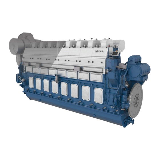
- Page 1 Wärtsilä 46F PRODUCT GUIDE...
- Page 2 © Copyright by WÄRTSILÄ FINLAND Oy COPYRIGHT © 2019 by WÄRTSILÄ FINLAND Oy All rights reserved. No part of this booklet may be reproduced or copied in any form or by any means (electronic, mechanical, graphic, photocopying, recording, taping or other information retrieval systems) without the prior written permission of the copyright owner.
- Page 3 For contracted projects specific instructions for planning the installation are always delivered. Any data and information herein is subject to revision without notice. This 2/2019 issue replaces all previous issues of the Wärtsilä 46F Product Guides. Issue Published...
- Page 4 This page intentionally left blank...
-
Page 5: Table Of Contents
Wärtsilä 46F Product Guide Table of contents Table of contents 1. Main Data and Outputs ..........................1.1 Maximum continuous output ....................... 1.2 Reference conditions ........................... 1.3 Operation in inclined position ......................1.4 Dimensions and weights ........................2. Operating Ranges ............................ - Page 6 Table of contents Wärtsilä 46F Product Guide 8. Compressed Air System .......................... 8.1 Instrument air quality ..........................8.2 Internal compressed air system ......................8.3 External compressed air system ......................9. Cooling Water System ..........................9.1 Water quality ............................9.2 Internal cooling water system ......................
- Page 7 Wärtsilä 46F Product Guide Table of contents 18.4 Required deck area for service work ....................18-7 19. Transport Dimensions and Weights ..................... 19-1 19.1 Lifting the in-line engine ........................19-1 19.2 Lifting the V-engine ..........................19-2 19.3 Engine components ...........................
- Page 8 This page intentionally left blank...
-
Page 9: Main Data And Outputs
Wärtsilä 46F Product Guide 1. Main Data and Outputs Main Data and Outputs The Wärtsilä 46F is a 4-stroke, non-reversible, turbocharged and intercooled diesel engine with direct fuel injection (twin pump). Cylinder bore 460 mm Stroke 580 mm Piston displacement 96.4 l/cyl... -
Page 10: Reference Conditions
1. Main Data and Outputs Wärtsilä 46F Product Guide Reference conditions The output is available up to an air temperature of max. 45°C. For higher temperatures, the output has to be reduced according to the formula stated in ISO 3046-1:2002 (E). -
Page 11: Dimensions And Weights
Wärtsilä 46F Product Guide 1. Main Data and Outputs Dimensions and weights Fig 1-1 In-line engines (DAAE012051c) Engine LE1* LE3* LE5* 6L46F 8470 8620 6170 1320 1550 3500 1430 7L46F 9435 9440 6990 1465 1550 3800 1430 8L46F 10255 10260... - Page 12 1. Main Data and Outputs Wärtsilä 46F Product Guide Fig 1-2 V-engines (DAAE075826B) Engine LE1* LE3* LE5* 10945 10284 7600 1830 1952 3765* / 1620 12V46F 3770 14V46F 11728 8650 2347 4234 1620 16V46F 12871 9700 2347 4234 1620 Engine...
-
Page 13: Operating Ranges
Wärtsilä 46F Product Guide 2. Operating Ranges Operating Ranges Engine operating range Running below nominal speed the load must be limited according to the diagrams in this chapter in order to maintain engine operating parameters within acceptable limits. Operation in the shaded area is permitted only temporarily during transients. Minimum speed is indicated in the diagram, but project specific limitations may apply. -
Page 14: Loading Capacity
2. Operating Ranges Wärtsilä 46F Product Guide Loading capacity Controlled load increase is essential for highly supercharged diesel engines, because the turbocharger needs time to accelerate before it can deliver the required amount of air. A slower loading ramp than the maximum capability of the engine permits a more even temperature distribution in engine components during transients. -
Page 15: Operation At Low Load And Idling
Wärtsilä 46F Product Guide 2. Operating Ranges In normal operation the load should not be reduced from 100% to 0% in less than 15 seconds. When absolutely necessary, the load can be reduced as fast as the pitch setting system can react (overspeed due to windmilling must be considered for high speed ships). - Page 16 2. Operating Ranges Wärtsilä 46F Product Guide ● Maximum 10 minutes if the engine is to be stopped after the idling. 3 minutes idling before stop is recommended. ● Maximum 6 hours if the engine is to be loaded after the idling.
-
Page 17: Low Air Temperature
Wärtsilä 46F Product Guide 2. Operating Ranges rated output can be replaced by 2 times 30 minute engine operation at 70 % of the rated output. Note that shorter duration than 30 minutes is not recommended. Low air temperature The minimum inlet air temperature of 5°C applies, when the inlet air is taken from the engine room. - Page 18 This page intentionally left blank...
-
Page 19: Technical Data
Wärtsilä 46F Product Guide 3. Technical Data Technical Data Introduction This chapter contains technical data of the engine (heat balance, flows, pressures etc.) for design of auxiliary systems. Further design criteria for external equipment and system layouts are presented in the respective chapter. -
Page 20: Wärtsilä 6L46F
3. Technical Data Wärtsilä 46F Product Guide Wärtsilä 6L46F Wärtsilä 6L46F CPP Variable CPP Con- DE Constant Speed stant Speed Speed Cylinder output 1200 1200 1200 Engine speed Engine output 7200 7200 7200 Mean effective pressure 2.49 2.49 2.49 Combustion air system (Note 1) - Page 21 Wärtsilä 46F Product Guide 3. Technical Data Wärtsilä 6L46F CPP Variable CPP Con- DE Constant Speed stant Speed Speed Cylinder output 1200 1200 1200 Engine speed SFOC at 75% load (LFO) g/kWh 181.1 186.9 188.8 SFOC at 50% load (LFO) g/kWh 183.1...
- Page 22 3. Technical Data Wärtsilä 46F Product Guide Wärtsilä 6L46F CPP Variable CPP Con- DE Constant Speed stant Speed Speed Cylinder output 1200 1200 1200 Engine speed Starting air system (Note 5) Pressure, nom. (PT 301) 3000 3000 3000 Pressure at engine during start, min. (20°C)
-
Page 23: Wärtsilä 7L46F
Wärtsilä 46F Product Guide 3. Technical Data Wärtsilä 7L46F Wärtsilä 7L46F CPP Variable CPP Con- DE Constant Speed stant Speed Speed Cylinder output 1200 1200 1200 Engine speed Engine output 8400 8400 8400 Mean effective pressure 2.49 2.49 2.49 Combustion air system (Note 1) - Page 24 3. Technical Data Wärtsilä 46F Product Guide Wärtsilä 7L46F CPP Variable CPP Con- DE Constant Speed stant Speed Speed Cylinder output 1200 1200 1200 Engine speed SFOC at 75% load (LFO) g/kWh 181.1 186.9 188.8 SFOC at 50% load (LFO) g/kWh 183.1...
- Page 25 Wärtsilä 46F Product Guide 3. Technical Data Wärtsilä 7L46F CPP Variable CPP Con- DE Constant Speed stant Speed Speed Cylinder output 1200 1200 1200 Engine speed Starting air system (Note 5) Pressure, nom. (PT 301) 3000 3000 3000 Pressure at engine during start, min. (20°C)
-
Page 26: Wärtsilä 8L46F
3. Technical Data Wärtsilä 46F Product Guide Wärtsilä 8L46F Wärtsilä 8L46F CPP Variable CPP Con- DE Constant Speed stant Speed Speed Cylinder output 1200 1200 1200 Engine speed Engine output 9600 9600 9600 Mean effective pressure 2.49 2.49 2.49 Combustion air system (Note 1) - Page 27 Wärtsilä 46F Product Guide 3. Technical Data Wärtsilä 8L46F CPP Variable CPP Con- DE Constant Speed stant Speed Speed Cylinder output 1200 1200 1200 Engine speed SFOC at 75% load (LFO) g/kWh 181.1 186.9 188.8 SFOC at 50% load (LFO) g/kWh 183.1...
- Page 28 3. Technical Data Wärtsilä 46F Product Guide Wärtsilä 8L46F CPP Variable CPP Con- DE Constant Speed stant Speed Speed Cylinder output 1200 1200 1200 Engine speed Starting air system (Note 5) Pressure, nom. (PT 301) 3000 3000 3000 Pressure at engine during start, min. (20°C)
-
Page 29: Wärtsilä 9L46F
Wärtsilä 46F Product Guide 3. Technical Data Wärtsilä 9L46F Wärtsilä 9L46F CPP Variable CPP Con- DE Constant Speed stant Speed Speed Cylinder output 1200 1200 1200 Engine speed Engine output 10800 10800 10800 Mean effective pressure 2.49 2.49 2.49 Combustion air system (Note 1) - Page 30 3. Technical Data Wärtsilä 46F Product Guide Wärtsilä 9L46F CPP Variable CPP Con- DE Constant Speed stant Speed Speed Cylinder output 1200 1200 1200 Engine speed SFOC at 75% load (LFO) g/kWh 181.1 186.9 188.8 SFOC at 50% load (LFO) g/kWh 183.1...
- Page 31 Wärtsilä 46F Product Guide 3. Technical Data Wärtsilä 9L46F CPP Variable CPP Con- DE Constant Speed stant Speed Speed Cylinder output 1200 1200 1200 Engine speed Starting air system (Note 5) Pressure, nom. (PT 301) 3000 3000 3000 Pressure at engine during start, min. (20°C)
-
Page 32: Wärtsilä 12V46F
3. Technical Data Wärtsilä 46F Product Guide Wärtsilä 12V46F Wärtsilä 12V46F CPP Variable CPP Con- DE Constant Speed stant Speed Speed Cylinder output 1200 1200 1200 Engine speed Engine output 14400 14400 14400 Mean effective pressure 2.49 2.49 2.49 Combustion air system (Note 1) - Page 33 Wärtsilä 46F Product Guide 3. Technical Data Wärtsilä 12V46F CPP Variable CPP Con- DE Constant Speed stant Speed Speed Cylinder output 1200 1200 1200 Engine speed SFOC at 75% load (LFO) g/kWh 178.3 184.0 185.9 SFOC at 50% load (LFO) g/kWh 180.3...
- Page 34 3. Technical Data Wärtsilä 46F Product Guide Wärtsilä 12V46F CPP Variable CPP Con- DE Constant Speed stant Speed Speed Cylinder output 1200 1200 1200 Engine speed Starting air system (Note 5) Pressure, nom. (PT 301) 3000 3000 3000 Pressure at engine during start, min. (20°C)
-
Page 35: Wärtsilä 14V46F
Wärtsilä 46F Product Guide 3. Technical Data Wärtsilä 14V46F Wärtsilä 14V46F CPP Variable CPP Con- DE Constant Speed stant Speed Speed Cylinder output 1200 1200 1200 Engine speed Engine output 16800 16800 16800 Mean effective pressure 2.49 2.49 2.49 Combustion air system (Note 1) - Page 36 3. Technical Data Wärtsilä 46F Product Guide Wärtsilä 14V46F CPP Variable CPP Con- DE Constant Speed stant Speed Speed Cylinder output 1200 1200 1200 Engine speed SFOC at 75% load (LFO) g/kWh 178.3 184.0 185.9 SFOC at 50% load (LFO) g/kWh 180.3...
- Page 37 Wärtsilä 46F Product Guide 3. Technical Data Wärtsilä 14V46F CPP Variable CPP Con- DE Constant Speed stant Speed Speed Cylinder output 1200 1200 1200 Engine speed Starting air system (Note 5) Pressure, nom. (PT 301) 3000 3000 3000 Pressure at engine during start, min. (20°C)
-
Page 38: Wärtsilä 16V46F
3. Technical Data Wärtsilä 46F Product Guide Wärtsilä 16V46F Wärtsilä 16V46F CPP Variable CPP Con- DE Constant Speed stant Speed Speed Cylinder output 1200 1200 1200 Engine speed Engine output 19200 19200 19200 Mean effective pressure 2.49 2.49 2.49 Combustion air system (Note 1) - Page 39 Wärtsilä 46F Product Guide 3. Technical Data Wärtsilä 16V46F CPP Variable CPP Con- DE Constant Speed stant Speed Speed Cylinder output 1200 1200 1200 Engine speed SFOC at 75% load (LFO) g/kWh 178.3 184.0 185.9 SFOC at 50% load (LFO) g/kWh 180.3...
- Page 40 3. Technical Data Wärtsilä 46F Product Guide Wärtsilä 16V46F CPP Variable CPP Con- DE Constant Speed stant Speed Speed Cylinder output 1200 1200 1200 Engine speed Starting air system (Note 5) Pressure, nom. (PT 301) 3000 3000 3000 Pressure at engine during start, min. (20°C)
-
Page 41: Description Of The Engine
Wärtsilä 46F Product Guide 4. Description of the Engine Description of the Engine Definitions Fig 4-1 In-line engine and V-engine definitions (1V93C0029 / 1V93C0028) Main components and systems Main dimensions and weights are shown in section 1.4 Principal dimensions and weights. - Page 42 4. Description of the Engine Wärtsilä 46F Product Guide All crankshafts can be equipped with a torsional vibration damper at the free end of the engine, if required by the application. Full output is available also from the free end of the engine through a power-take-off (PTO).
- Page 43 The injection nozzles are cooled by lubricating oil. Wärtsilä 46F engines are equipped with twin plunger pumps that enable control of the injection timing. In addition to the timing control, the twin plunger solution also combines high mechanical strength with cost efficient design.
- Page 44 4. Description of the Engine Wärtsilä 46F Product Guide exhaust side. The wastegate arrangement permits a part of the exhaust gas to bypass the turbine in the turbocharger at high engine load. Variable speed engines are additionally equipped with a by-pass valve to increase the flow through the turbocharger at low engine speed and low engine load.
-
Page 45: Cross Section Of The Engine
Wärtsilä 46F Product Guide 4. Description of the Engine Cross section of the engine Fig 4-2 Cross section of the in-line engine DAAB605814... - Page 46 4. Description of the Engine Wärtsilä 46F Product Guide Fig 4-3 Cross section of the V-engine DAAB605814...
-
Page 47: Overhaul Intervals And Expected Life Times
Wärtsilä 46F Product Guide 4. Description of the Engine Overhaul intervals and expected life times The following overhaul intervals and lifetimes are for guidance only. Achievable lifetimes depend on operating conditions, average loading of the engine, fuel quality used, fuel handling system, performance of maintenance etc. -
Page 48: Engine Storage
4. Description of the Engine Wärtsilä 46F Product Guide Component Expected life time (h) LFO operation HFO1 operation HFO2 operation - Inlet valve seat 36000 36000 36000 - Inlet valve, guide and rotator 24000 24000 24000 - Exhaust valve seat... -
Page 49: Piping Design, Treatment And Installation
Wärtsilä 46F Product Guide 5. Piping Design, Treatment and Installation Piping Design, Treatment and Installation This chapter provides general guidelines for the design, construction and installation of piping systems, however, not excluding other solutions of at least equal standard. Fuel, lubricating oil, fresh water and compressed air piping is usually made in seamless carbon steel (DIN 2448) and seamless precision tubes in carbon or stainless steel (DIN 2391), exhaust gas piping in welded pipes of corten or carbon steel (DIN 2458). -
Page 50: Trace Heating
5. Piping Design, Treatment and Installation Wärtsilä 46F Product Guide Piping Pipe material Max velocity [m/s] Sea water piping Galvanized steel Aluminium brass 10/90 copper-nickel-iron 70/30 copper-nickel Rubber lined pipes Compressed air pipe sizing has to be calculated project specifically. The pipe sizes may be chosen on the basis of air velocity or pressure drop. -
Page 51: Pipe Class
Wärtsilä 46F Product Guide 5. Piping Design, Treatment and Installation pressure of the circulating pumps may rise to 1.05 MPa (10.5 bar), and the safety valve of the pump shall thus be adjusted e.g. to 1.2 MPa (12 bar). ● A design pressure of not less than 1.2 MPa (12 bar) has to be selected. -
Page 52: Local Gauges
5. Piping Design, Treatment and Installation Wärtsilä 46F Product Guide ● Pipes between engine and jacket water preheater Local gauges Local thermometers should be installed wherever a new temperature occurs, i.e. before and after heat exchangers, etc. Pressure gauges should be installed on the suction and discharge side of each pump. -
Page 53: Flexible Pipe Connections
Wärtsilä 46F Product Guide 5. Piping Design, Treatment and Installation nominal flow. Heaters, automatic filters and the viscosimeter should be bypassed to prevent damage caused by debris in the piping. The automatic fuel filter must not be used as flushing filter. -
Page 54: Clamping Of Pipes
5. Piping Design, Treatment and Installation Wärtsilä 46F Product Guide ● If not otherwise instructed, bolts are to be tightened crosswise in several stages ● Painting of flexible elements is not allowed ● Rubber bellows must be kept clean from oil and fuel ●... - Page 55 Wärtsilä 46F Product Guide 5. Piping Design, Treatment and Installation ● The first support should be located as close as possible to the flexible connection. Next support should be 0.3-0.5 m from the first support. ● First three supports closest to the engine or generating set should be fixed supports. Where necessary, sliding supports can be used after these three fixed supports to allow thermal expansion of the pipe.
- Page 56 5. Piping Design, Treatment and Installation Wärtsilä 46F Product Guide Fig 5-3 Pipe clamp for fixed support (V61H0842A) DAAB605814...
-
Page 57: Fuel Oil System
Wärtsilä 46F Product Guide 6. Fuel Oil System Fuel Oil System Acceptable fuel characteristics The fuel specifications are based on the ISO 8217:2017 (E) standard. Observe that a few additional properties not included in the standard are listed in the tables. For maximum fuel temperature before the engine, see chapter "Technical Data". - Page 58 6. Fuel Oil System Wärtsilä 46F Product Guide Test meth- Category ISO-F Lim- Characteristics Unit od(s) and ref- D M A D M Z D M B erences Cetane index ISO 4264 ISO 8754 or b, k) Sulphur 1,00 1,00...
- Page 59 Wärtsilä 46F Product Guide 6. Fuel Oil System NOTE a) 1 mm²/s = 1 cSt. b) Notwithstanding the limits given, the purchaser shall define the maximum sulphur content in accordance with relevant statutory limitations. c) If the sample is not clear and bright, the total sediment by hot filtration and water tests shall be required.
- Page 60 DM grade category requirements, though from their properties point of view this is generally not an optimum approach. These fuels can be used in the Wärtsilä® 46F engine type, but special attention shall be paid to optimum operating conditions. See also Services Instruction WS02Q312.
- Page 61 Wärtsilä 46F Product Guide 6. Fuel Oil System Test method refer- Characteristics Unit RMA 10 RMB 30 RMD 80 ence Used lubricating oil: - Calcium, max. mg/kg IP 501 or IP 470 mg/kg IP 501 or IP 470 - Zinc, max.
- Page 62 6. Fuel Oil System Wärtsilä 46F Product Guide 6.1.3 Heavy fuel oil operation (residual) The fuel specification “HFO 2” is based on the ISO 8217:2017(E) standard and covers the fuel categories ISO-F-RMA 10 – RMK 700. Additionally, the engine manufacturer has specified the fuel specification “HFO 1”.
- Page 63 Wärtsilä 46F Product Guide 6. Fuel Oil System NOTE a) Max. 1010 kg/m³ at 15 °C, provided the fuel treatment system can reduce water and solids (sediment, sodium, aluminium, silicon) before engine to the specified levels. b) 1 mm²/s = 1 cSt.
-
Page 64: Internal Fuel Oil System
6. Fuel Oil System Wärtsilä 46F Product Guide Internal fuel oil system Fig 6-1 Internal fuel system, in-line engine (DAAF424885) System components Injection pump Fuel oil leakage collector Injection valve Flywheel Pressure control valve Turning device Pulse damper Fuel and timing rack... - Page 65 Wärtsilä 46F Product Guide 6. Fuel Oil System Fig 6-2 Internal fuel system, V-engine (DAAR030664) System components Injection pump Fuel & timing rack Flywheel Injection valve Pulse damper Camshaft Switching valve Fuel oil leakage collector Pressure regulating valve Sensors and indicators...
-
Page 66: External Fuel Oil System
6. Fuel Oil System Wärtsilä 46F Product Guide A pressure control valve in the fuel return line on the engine maintains desired pressure before the injection pumps. 6.2.1 Leak fuel system Clean leak fuel from the injection valves and the injection pumps is collected on the engine and drained by gravity through a clean leak fuel connection (103) . - Page 67 Wärtsilä 46F Product Guide 6. Fuel Oil System - Example: ß = 75 means “every 75 particles 20 micron ISO dust sent, one passes”. - Efficiency εxx = YY % : same meaning as Beta-value, but not any ISO standardised test method, hence sometimes used for particles larger than 25..45 micron.
- Page 68 6. Fuel Oil System Wärtsilä 46F Product Guide Fig 6-3 Fuel oil viscosity-temperature diagram for determining the pre-heating temperatures of fuel oils (4V92G0071b) Example 1: A fuel oil with a viscosity of 380 cSt (A) at 50°C (B) or 80 cSt at 80°C (C) must be pre-heated to 115 - 130°C (D-E) before the fuel injection pumps, to 98°C (F) at the separator...
- Page 69 Wärtsilä 46F Product Guide 6. Fuel Oil System To ensure sufficient time for settling (water and sediment separation), the capacity of each tank should be sufficient for min. 24 hours operation at maximum fuel consumption. The tanks should be provided with internal baffles to achieve efficient settling and have a sloped bottom for proper draining.
- Page 70 6. Fuel Oil System Wärtsilä 46F Product Guide 6.3.4 Fuel treatment 6.3.4.1 Separation Heavy fuel (residual, and mixtures of residuals and distillates) must be cleaned in an efficient centrifugal separator before it is transferred to the day tank. Classification rules require the separator arrangement to be redundant so that required capacity is maintained with any one unit out of operation.
- Page 71 Wärtsilä 46F Product Guide 6. Fuel Oil System ● Feed pump (1P02) ● Pre-heater (1E01) ● Sludge tank (1T05) ● Separator (1S01/1S02) ● Sludge pump ● Control cabinets including motor starters and monitoring Fig 6-4 Fuel transfer and separating system (V76F6626G) 6.3.4.3...
- Page 72 6. Fuel Oil System Wärtsilä 46F Product Guide Design temperature 100°C 50°C Viscosity for dimensioning electric motor 1000 cSt 100 cSt 6.3.4.4 Separator pre-heater (1E01) The pre-heater is dimensioned according to the feed pump capacity and a given settling tank temperature.
- Page 73 Wärtsilä 46F Product Guide 6. Fuel Oil System 6.3.4.6 MDF separator in HFO installations (1S02) A separator for MDF is recommended also for installations operating primarily on HFO. The MDF separator can be a smaller size dedicated MDF separator, or a stand-by HFO separator used for MDF.
- Page 74 6. Fuel Oil System Wärtsilä 46F Product Guide Pipe connections Fuel outlet Leak fuel drain, clean fuel Leak fuel drain, dirty fuel Fig 6-6 Example of fuel oil system, MDF (DAAF42894) System components Pipe connections 1E04 Cooler (MDF) Fuel inlet...
- Page 75 Wärtsilä 46F Product Guide 6. Fuel Oil System 6.3.5.1 Circulation pump, MDF (1P03) The circulation pump maintains the pressure at the injection pumps and circulates the fuel in the system. It is recommended to use a screw pump as circulation pump. A suction strainer with a fineness of 0.5 mm should be installed before each pump.
- Page 76 6. Fuel Oil System Wärtsilä 46F Product Guide 6.3.5.4 MDF cooler (1E04) The fuel viscosity may not drop below the minimum value stated in Technical data. When operating on MDF, the practical consequence is that the fuel oil inlet temperature must be kept below 45°C.
- Page 77 Wärtsilä 46F Product Guide 6. Fuel Oil System 6.3.6 Fuel feed system - HFO installations Fig 6-7 Example of fuel oil system, HFO (DAAF424853) System components Diesel engine Wärtsilä V46F 1N01 Feeder/booster unit Diesel engine Wärtsilä L46F 1P04 Fuel feed pump (Booster Unit)
- Page 78 6. Fuel Oil System Wärtsilä 46F Product Guide Fig 6-8 Example of fuel oil system, HFO (DAAF424854) System components Diesel engine Wärtsilä V46F 1P04 Fuel feed pump (Booster Unit) Diesel engine Wärtsilä L46F 1P06 Circulation pump (Booster unit) Adapter 1P12...
- Page 79 Wärtsilä 46F Product Guide 6. Fuel Oil System HFO pipes shall be properly insulated. If the viscosity of the fuel is 180 cSt/50°C or higher, the pipes must be equipped with trace heating. It shall be possible to shut off the heating of the pipes when operating on MDF (trace heating to be grouped logically).
- Page 80 6. Fuel Oil System Wärtsilä 46F Product Guide ● One viscosimeter for control of the heaters ● One control valve for steam or thermal oil heaters, a control cabinet for electric heaters ● One temperature sensor for emergency control of the heaters ●...
- Page 81 Wärtsilä 46F Product Guide 6. Fuel Oil System Total consumption of the connected engines added with Capacity the flush quantity of the automatic filter (1F08) and 15% margin. Design pressure 1.6 MPa (16 bar) Max. total pressure (safety valve) 0.7 MPa (7 bar) Design temperature 100°C...
- Page 82 6. Fuel Oil System Wärtsilä 46F Product Guide a multiple engine installation, two flow meters per engine are to be installed: one in the feed line and one in the return line of each engine. There should be a by-pass line around the consumption meter, which opens automatically in case of excessive pressure drop.
- Page 83 Wärtsilä 46F Product Guide 6. Fuel Oil System Viscosity for dimensioning of electric motor 500 cSt Heater, booster unit (1E02) The heater must be able to maintain a fuel viscosity of 14 cSt at maximum fuel consumption, with fuel of the specified grade and a given day tank temperature (required viscosity at injection pumps stated in Technical data).
- Page 84 6. Fuel Oil System Wärtsilä 46F Product Guide Frequency converter: - Not needed - HFO engines - Required - Bi - fuel engines Design pressure 1.6 MPa (16 bar) Design temperature 150°C Pressure for dimensioning of electric motor (ΔP): - if all fuel is fed through feeder/booster unit 0.3 MPa (3 bar)
- Page 85 Wärtsilä 46F Product Guide 6. Fuel Oil System The fuel pipes at the engine (connections 101 and 102) are disconnected and the supply and return lines are connected with a temporary pipe or hose on the installation side. All filter inserts are removed, except in the flushing filter of course.
- Page 86 This page intentionally left blank...
-
Page 87: Lubricating Oil System
Wärtsilä 46F Product Guide 7. Lubricating Oil System Lubricating Oil System Lubricating oil requirements 7.1.1 Engine lubricating oil The lubricating oil must be of viscosity class SAE 40 and have a viscosity index (VI) of minimum 95. The lubricating oil alkalinity (BN) is tied to the fuel grade, as shown in the table below. BN is an abbreviation of Base Number. -
Page 88: Internal Lubricating Oil System
7. Lubricating Oil System Wärtsilä 46F Product Guide Optimum BN in this kind of operation depends on the length of operating periods on both fuel qualities as well as of sulphur content of fuels in question. Thus in particular cases BN 40 or even higher BN lubricating oils should be used. - Page 89 Wärtsilä 46F Product Guide 7. Lubricating Oil System Sensors and indicators PT201 Lube oil pressure, engine inlet T E 7 0 1 6 A . . 7 0 9 6 A Big end bearing temperature TE201 Lube oil temperature, engine inlet...
- Page 90 7. Lubricating Oil System Wärtsilä 46F Product Guide Sensors and indicators PTZ201 Lube oil pressure, engine inlet TE272 Lube oil temperature, TC A outlet TE201 Lube oil temperature, engine inlet PT700 Crankcase pressure TI201 Lube oil temperature, engine inlet (local)
-
Page 91: External Lubricating Oil System
Wärtsilä 46F Product Guide 7. Lubricating Oil System External lubricating oil system Fig 7-3 External lubricating oil system, engine driven & stand by pumps (DAAF423923) System components Diesel engine Wärtsilä L46F 2N01 Separator unit Pressure control valve 2P02 Pre-lubricating oil pump... - Page 92 7. Lubricating Oil System Wärtsilä 46F Product Guide Fig 7-4 External lubricating oil system, engine driven & stand by pumps (DAAF423924) System components: Diesel engine Wärtsilä L46F 2P02 Pre-lubricating oil pump Pressure control valve 2P03 Separator pump (Separator unit) 2H0X...
- Page 93 Wärtsilä 46F Product Guide 7. Lubricating Oil System Pipe connections: Crankcase ventilation Two outlets in each end are available Fig 7-5 External lubricating oil system, without engine built automatic filter (DAAF423925) System components: Diesel engine Wärtsilä L46F 2P03 Separator pump (Separator unit)
- Page 94 7. Lubricating Oil System Wärtsilä 46F Product Guide Pipe connections: Lube oil inlet (to manifold) Lubricating oil outlet Lube oil to engine driven pump Lube oil from priming pump Lubricating oil from electric driven pump Lube oil from cooler Lube oil sample...
- Page 95 Wärtsilä 46F Product Guide 7. Lubricating Oil System System components: 2F01 Suction strainer (main lube pump) 2P04 Stand-by pump 2F02 Automatic filter (LO) 2T01 System oil tank 2F03 Suction strainer (separator unit) 2T06 Sludge tank 2F04 Suction strainer (pre lubricating...
- Page 96 7. Lubricating Oil System Wärtsilä 46F Product Guide located in the ship's bottom is normally 65...75°C. To enable separation with a stopped engine the heater capacity must be sufficient to maintain the required temperature without heat supply from the engine.
- Page 97 Wärtsilä 46F Product Guide 7. Lubricating Oil System lubricating oil pump. The suction pipe shall further be equipped with a non-return valve of flap type without spring. The non-return valve is particularly important with engine driven pump and it must be installed in such a position that self-closing is ensured.
- Page 98 7. Lubricating Oil System Wärtsilä 46F Product Guide 7.3.3 Suction strainers (2F01, 2F04, 2F06) It is recommended to install a suction strainer before each pump to protect the pump from damage. The suction strainer and the suction pipe must be amply dimensioned to minimize pressure losses.
- Page 99 Wärtsilä 46F Product Guide 7. Lubricating Oil System Max. pressure (safety valve) 350 kPa (3.5 bar) Design temperature 100°C Viscosity for dimensioning of the electric 500 cSt motor DAAB605814 7-13...
- Page 100 7. Lubricating Oil System Wärtsilä 46F Product Guide Example of required power, oil temperature 40°C. 6L46F 7L46F 8L46F 9L46F 12V46F 14V46F 16V46F Pump [kW] 11.5 11.5 Electric motor [kW] Example of required power, oil temperature 20°C. 6L46F 7L46F 8L46F 9L46F...
-
Page 101: Crankcase Ventilation System
Wärtsilä 46F Product Guide 7. Lubricating Oil System Fineness (absolute) max. 60 µm (mesh size) Maximum permitted pressure drop at 50 cSt: - clean filter 30 kPa (0.3 bar ) - alarm 80 kPa (0.8 bar) 7.3.8 Automatic filter, backflush flow (2F13) -
Page 102: Flushing Instructions
7. Lubricating Oil System Wärtsilä 46F Product Guide Design data: Flow see Technical data Backpressure, max. see Technical data Temperature 80°C The size of the ventilation pipe (D2) out from the condensate trap should be bigger than the ventilation pipe (D) com- ing from the engine. - Page 103 Wärtsilä 46F Product Guide 7. Lubricating Oil System 7.5.3.3 Flushing with low viscosity flushing oil If no separator heating is available during the flushing procedure it is possible to use a low viscosity flushing oil instead of engine oil. In such a case the low viscosity flushing oil must be disposed of after completed flushing.
- Page 104 This page intentionally left blank...
-
Page 105: Compressed Air System
Wärtsilä 46F Product Guide 8. Compressed Air System Compressed Air System Compressed air is used to start engines and to provide actuating energy for safety and control devices. The use of starting air for other purposes is limited by the classification regulations. - Page 106 8. Compressed Air System Wärtsilä 46F Product Guide Fig 8-1 Internal compressed air system, in-line engine (DAAF424886) System components Main starting valve Pilot controlled valves for stopping Flame arrestor Pneumatic stopping cylinders Starting air valve in cylinder head Oil mist detector...
- Page 107 Wärtsilä 46F Product Guide 8. Compressed Air System Sensors and indicators GT519 Exhaust wastegate valve position PT320 Air wastegate air pressure, 4-8 BAR CV6560-1 Air wastegate valve, open QU700 Oil mist detector CV6560-2 Air wastegate valve, open NS700 Oil mist detector failure...
- Page 108 8. Compressed Air System Wärtsilä 46F Product Guide Fig 8-2 Internal compressed air system, V-engine (DAAR030690) System components Main starting valve Blocking valve for turning gear Flame arrester Switching valve Starting air valve in cylinder head Pilot controlled valves for stopping...
- Page 109 Wärtsilä 46F Product Guide 8. Compressed Air System Pipe connections Control air to air wastegate valve, 4-8 bar * If variable speed engine or artic conditions ** if SCR or arctic conditions DAAB605814...
-
Page 110: External Compressed Air System
8. Compressed Air System Wärtsilä 46F Product Guide External compressed air system The design of the starting air system is partly determined by classification regulations. Most classification societies require that the total capacity is divided into two equally sized starting air receivers and starting air compressors. - Page 111 Wärtsilä 46F Product Guide 8. Compressed Air System Pipe connections Control air to by-pass/waste-gate valve Air supply for flushing Instrument air inlet 8.3.1 Starting air compressor unit (3N02) At least two starting air compressors must be installed. It is recommended that the compressors are capable of filling the starting air vessel from minimum (1.8 MPa) to maximum pressure in...
- Page 112 8. Compressed Air System Wärtsilä 46F Product Guide The starting air consumption stated in technical data is for a successful start. During start the main starting valve is kept open until the engine starts, or until the max. time for the starting attempt has elapsed.
-
Page 113: Cooling Water System
Wärtsilä 46F Product Guide 9. Cooling Water System Cooling Water System Water quality The fresh water in the cooling water system of the engine must fulfil the following requirements: p H ....... min. 6.5...8.5 Hardness ..... max. 10 °dH Chlorides ..... -
Page 114: Internal Cooling Water System
9. Cooling Water System Wärtsilä 46F Product Guide Internal cooling water system Fig 9-1 Internal cooling water system, in-line engine (DAAF420187) System components Cylinder head Lubricating oil cooler Charge air cooler (HT) HT water pump (engine driven) Charge air cooler (LT) - Page 115 Wärtsilä 46F Product Guide 9. Cooling Water System Fig 9-2 Internal cooling water system, V-engine (DAAR011165B) System components, in-line engines Cylinder head Lubricating oil cooler Charge air cooler (HT) LT water pump (engine driven) Charge air cooler (LT) HT water pump (engine driven)
- Page 116 9. Cooling Water System Wärtsilä 46F Product Guide Pipe connections, in-line engines LT-water outlet LT-water air vent from air cooler LT-water from stand by pump LT-water air vent DAAB605814...
- Page 117 Wärtsilä 46F Product Guide 9. Cooling Water System The fresh water cooling system is divided into a high temperature (HT) and a low temperature (LT) circuit. The HT water circulates through cylinder jackets, cylinder heads and the 1st stage of the charge air cooler. The HT water passes through the cylinder jackets before it enters the HT-stage of the charge air cooler.
-
Page 118: External Cooling Water System
9. Cooling Water System Wärtsilä 46F Product Guide External cooling water system It is recommended to divide the engines into several circuits in multi-engine installations. One reason is of course redundancy, but it is also easier to tune the individual flows in a smaller system. - Page 119 Wärtsilä 46F Product Guide 9. Cooling Water System Fig 9-5 External cooling water system (DAAF424312) System components 4E05 Heater (pre-heating unit) 4P09 Transfer pump 4E08 Central cooler 4P14 / Circulation pump (HT) / (LT) 4P15 4E12 Cooler (installation equipment) 4S01...
- Page 120 9. Cooling Water System Wärtsilä 46F Product Guide System components 4P03 Stand-by pump (HT) 4V02 Temperature control valve (heat recovery) 4P04 Circulation pump (preheater) 4V08 Temperature control valve (central cooler) 4P05 Stand-by pump (LT) In case of turbocharger at driving end...
- Page 121 Wärtsilä 46F Product Guide 9. Cooling Water System Fig 9-6 External cooling water system ( DAAF424313) System components 4E05 Heater (preheater) 4P14 / Circulating pump (HT) / (LT) 4P15 4E08 Central cooler 4S01 Air venting 4E12 Cooler (installation equipment) 4T03...
- Page 122 9. Cooling Water System Wärtsilä 46F Product Guide Fig 9-7 External cooling water system (DAAF424314) The drain line from connection 411 should have a continuous slope downwards to the cooling water drain tank. The vent pipes should have a continuous slope upwards to the expansion tank.
- Page 123 Wärtsilä 46F Product Guide 9. Cooling Water System System components 4E05 Heater (preheater) 4P14 / Circulating pump (HT) / (LT) 4P15 4E06 Raw water cooler (LT) 4S02 / Air dearator (HT) / (LT) 4S03 4H0X Flexible pipe connections 4T01 /...
- Page 124 9. Cooling Water System Wärtsilä 46F Product Guide Fig 9-8 External cooling water system (DAAF424315) System components 4E08 Central cooler 4S01 Air venting 4E10 Cooler (reduction gear) 4T03 Additive dosing tank 4E12 Cooler (installation equipment) 4T04 Drain tank 4N01 Preheating unit...
- Page 125 Wärtsilä 46F Product Guide 9. Cooling Water System Fig 9-9 Sea water system DAAE020523 System components 4E08 Central cooler 4F01 Suction strainer (sea water) 4P11 Circulation pump (sea water) Ships (with ice class) designed for cold sea-water should have provisions for recirculation back to the sea chest from the central cooler: ●...
- Page 126 9. Cooling Water System Wärtsilä 46F Product Guide 9.3.2 Sea water pump (4P11) The sea water pumps are always separate from the engine and electrically driven. The capacity of the pumps is determined by the type of coolers and the amount of heat to be dissipated.
- Page 127 Wärtsilä 46F Product Guide 9. Cooling Water System Fresh water temperature after cooler max. 38°C Margin (heat rate, fouling) Fig 9-10 Central cooler main dimensions. Example for guidance only Engine type A [mm] C [mm] D [mm] Weight [kg] 6L46F...
- Page 128 9. Cooling Water System Wärtsilä 46F Product Guide Venting pipes to the expansion tank are to be installed at all high points in the piping system, where air or gas can accumulate. The vent pipes must be continuously rising. 9-16...
- Page 129 Wärtsilä 46F Product Guide 9. Cooling Water System Fig 9-11 Example of air venting device (V60D0343) 9.3.9 Expansion tank (4T05) The expansion tank compensates for thermal expansion of the coolant, serves for venting of the circuits and provides a sufficient static pressure for the circulating pumps.
- Page 130 9. Cooling Water System Wärtsilä 46F Product Guide The expansion tank should be equipped with an inspection hatch, a level gauge, a low level alarm and necessary means for dosing of cooling water additives. The vent pipes should enter the tank below the water level. The vent pipes must be drawn separately to the tank (see air venting) and the pipes should be provided with labels at the expansion tank.
- Page 131 Wärtsilä 46F Product Guide 9. Cooling Water System It is recommended to heat the HT water to a temperature near the normal operating temperature. The heating power determines the required time to heat up the engine from cold condition. The minimum required heating power is 12 kW/cyl, which makes it possible to warm up the engine from 20 ºC to 60...70 ºC in 10-15 hours.
- Page 132 9. Cooling Water System Wärtsilä 46F Product Guide Fig 9-12 Example of preheating unit, electric (4V47K0045) Table 9-2 Example of preheating unit Capacity [kW] Water content [kg] Weight [kg] 1455 1455 1445 1000 1645 1000 1100 1640 1100 1100 1640...
- Page 133 Wärtsilä 46F Product Guide 9. Cooling Water System Fig 9-13 Example of preheating unit, steam Type L1 [mm] L2 [mm] Dry weight [kg] KVDS-72 1160 KVDS-96 1160 KVDS-108 1160 KVDS-135 1210 KVDS-150 1210 KVDS-170 1190 1210 KVDS-200 1190 1260 KVDS-240...
- Page 134 9. Cooling Water System Wärtsilä 46F Product Guide 9.3.14 Thermometers and pressure gauges Local thermometers should be installed wherever there is a temperature change, i.e. before and after heat exchangers etc. in external system. Local pressure gauges should be installed on the suction and discharge side of each pump.
-
Page 135: Combustion Air System
Wärtsilä 46F Product Guide 10. Combustion Air System Combustion Air System 10.1 Engine room ventilation To maintain acceptable operating conditions for the engines and to ensure trouble free operation of all equipment, attention shall be paid to the engine room ventilation and the supply of combustion air. - Page 136 10. Combustion Air System Wärtsilä 46F Product Guide It is good practice to provide areas with significant heat sources, such as separator rooms with their own air supply and extractors. Under-cooling of the engine room should be avoided during all conditions (service conditions, slow steaming and in port).
-
Page 137: Combustion Air System Design
Wärtsilä 46F Product Guide 10. Combustion Air System Fig 10-2 Engine room ventilation, air duct connected to the turbocharger (DAAE092652A) 10.2 Combustion air system design Usually, the combustion air is taken from the engine room through a filter on the turbocharger. - Page 138 10. Combustion Air System Wärtsilä 46F Product Guide a flap for controlling the direction and amount of air. Also other combustion air consumers, for example other engines, gas turbines and boilers shall be served by dedicated combustion air ducts. If necessary, the combustion air duct can be connected directly to the turbocharger with a flexible connection piece.
-
Page 139: Exhaust Gas System
Wärtsilä 46F Product Guide 11. Exhaust Gas System Exhaust Gas System 11.1 Internal exhaust gas system Fig 11-1 Charge air and exhaust gas system, in-line engines (DAAF422688) System components Air filter Orifice Turbocharger Cylinder head Charge air cooler (HT) Exhaust waste gate valve... - Page 140 11. Exhaust Gas System Wärtsilä 46F Product Guide Fig 11-2 Charge air and exhaust gas system, V-engines (DAAR011167) System components Air filter Turbine Compressor Wastegate valve (CV519) Charge air cooler (HT) Water mist catcher Charge air cooler (LT) By-pass valve (CV643)
- Page 141 Wärtsilä 46F Product Guide 11. Exhaust Gas System Pipe connections Size 607A Condensate water after charge air cooler, A-bank OD22 607B Condensate water after charge air cooler, B-bank OD22 Scavenging air outlet to TC cleaning valve unit OD18 DAAB605814 11-3...
-
Page 142: Exhaust Gas Outlet
11. Exhaust Gas System Wärtsilä 46F Product Guide 11.2 Exhaust gas outlet Exhaust gas outlet pipe connection is available with 0° orientation for all engine configurations. Exhaust gas outlet pipe connection with 45° degree orientation is achievable with additional bellows. -
Page 143: External Exhaust Gas System
Wärtsilä 46F Product Guide 11. Exhaust Gas System 11.3 External exhaust gas system Each engine should have its own exhaust pipe into open air. Backpressure, thermal expansion and supporting are some of the decisive design factors. Flexible bellows must be installed directly on the turbocharger outlet, to compensate for thermal expansion and prevent damages to the turbocharger due to vibrations. - Page 144 11. Exhaust Gas System Wärtsilä 46F Product Guide The exhaust pipe must be insulated with insulation material approved for concerned operation conditions, minimum thickness 30 mm considering the shape of engine mounted insulation. Insulation has to be continuous and protected by a covering plate or similar to keep the insulation intact.
- Page 145 Wärtsilä 46F Product Guide 11. Exhaust Gas System must be made to ensure that water cannot spill down into the SCR, when the exhaust boiler is cleaned with water. More information about the SCR-unit can be found in the Wärtsilä Environmental Product Guide.
- Page 146 11. Exhaust Gas System Wärtsilä 46F Product Guide 11.3.7 Exhaust gas silencers The exhaust gas silencing can be accomplished either by the patented Compact Silencer System (CSS) technology or by the conventional exhaust gas silencer. 11.3.7.1 Exhaust noise The unattenuated exhaust noise is typically measured in the exhaust duct. The in-duct measurement is transformed into free field sound power through a number of correction factors.
- Page 147 Wärtsilä 46F Product Guide 11. Exhaust Gas System 11.3.7.2 Silencer system comparison With a conventional silencer system, the design of the noise reduction system usually starts from the engine. With the CSS, the design is reversed, meaning that the noise level acceptability at a certain distance from the ship's exhaust gas pipe outlet, is used to dimension the noise reduction system.
- Page 148 11. Exhaust Gas System Wärtsilä 46F Product Guide 11.3.7.4 Conventional exhaust gas silencer (5R02) Yard/designer should take into account that unfavourable layout of the exhaust system (length of straight parts in the exhaust system) might cause amplification of the exhaust noise between engine outlet and the silencer.
-
Page 149: Turbocharger Cleaning
Additives, solvents or salt water must not be used and the cleaning instructions in the operation manual must be carefully followed. Wärtsilä 46F engines are delivered with an automatic cleaning system, which comprises a valve unit mounted in the engine room close to the turbocharger and a common control unit for up to six engines. - Page 150 12. Turbocharger Cleaning Wärtsilä 46F Product Guide System components: 5Z03 TC cleaning device Air filter TC wash control unit Male stud GR18LR71 Flow meter/control Constant flow valve Engine Water Flow meter Engine Turbocharger Water inlet press Nom water inlet Water inlet flow...
-
Page 151: Exhaust Emissions
Wärtsilä 46F Product Guide 13. Exhaust Emissions Exhaust Emissions Exhaust emissions from the diesel engine mainly consist of nitrogen, oxygen and combustion products like carbon dioxide (CO ), water vapour and minor quantities of carbon monoxide (CO), sulphur oxides (SO... -
Page 152: Marine Exhaust Emissions Legislation
13. Exhaust Emissions Wärtsilä 46F Product Guide of the incomplete combustion of the fuel or lubricating oil. White smoke is usually condensed water vapour. Yellow smoke is caused by NO emissions. When the exhaust gas is cooled significantly prior to discharge to the atmosphere, the condensed NO component can have a brown appearance. -
Page 153: Methods To Reduce Exhaust Emissions
Wärtsilä 46F Product Guide 13. Exhaust Emissions 13.3 Methods to reduce exhaust emissions All standard Wärtsilä engines meet the NOx emission level set by the IMO (International Maritime Organisation) and most of the local emission levels without any modifications. Wärtsilä has also developed solutions to significantly reduce NOx emissions when this is required. - Page 154 This page intentionally left blank...
-
Page 155: Automation System
Wärtsilä 46F Product Guide 14. Automation System Automation System Wärtsilä Unified Controls - UNIC is a fully embedded and distributed engine management system, which handles all control functions on the engine; for example start sequencing, start blocking, fuel injection, speed control, load sharing, normal stops and safety shutdowns. - Page 156 14. Automation System Wärtsilä 46F Product Guide Input/Output Module handles measurements and limited control functions in a specific area on the engine. Cylinder Control Module handles fuel injection control and local measurements for the cylinders. Engine Safety Module handles fundamental engine safety, for example shutdown due to overspeed or low lubricating oil pressure.
-
Page 157: Functions
Wärtsilä 46F Product Guide 14. Automation System ● Led indication of status and detected faults ● Digital status outputs ● Shutdown latching and reset ● Shutdown pre-warning ● Shutdown override (configuration depending on application) 14.1.5 Power unit A power unit is delivered with each engine. The power unit supplies DC power to the automation system on the engine and provides isolation from other power supply systems onboard. - Page 158 14. Automation System Wärtsilä 46F Product Guide 14.2.2 Stop and shutdown A normal stop can be initiated locally, or remotely if applicable for the installation. At normal stop the stop sequence is active until the engine has come to standstill. Thereafter the system automatically returns to “ready for start”...
-
Page 159: Alarm And Monitoring Signals
Wärtsilä 46F Product Guide 14. Automation System with tie breakers between the different sections, then the status of each tie breaker is required for control of the load sharing in isochronous mode. 14.3 Alarm and monitoring signals Regarding sensors on the engine, the actual configuration of signals and the alarm levels are found in the project specific documentation supplied for all contracted projects. - Page 160 14. Automation System Wärtsilä 46F Product Guide 14.4.1.5 Stand-by pump, LT cooling water (if applicable) (4P05) The engine control system starts the pump automatically via a motor starter, if the cooling water pressure drops below a preset level when the engine is running. There is a dedicated sensor on the engine for this purpose.
-
Page 161: Guideline For Electrical And Automation System
Wärtsilä 46F Product Guide 14. Automation System 14.5 Guideline for electrical and automation system Load increase during ship acceleration, manoeuvring, and load transfer between generators must be controlled according to instructions in chapter 2.2 Loading Capacity. The total load increase rate on a recently connected generator (preheated engine) is the sum of the uploading that is performed by the load sharing control and by the propulsion control. - Page 162 This page intentionally left blank...
-
Page 163: Foundation
Wärtsilä 46F Product Guide 15. Foundation Foundation Engines can be either rigidly mounted on chocks, or resiliently mounted on steel spring elements. If resilient mounting is considered, Wärtsilä must be informed about existing excitations such as propeller blade passing frequency. Dynamic forces caused by the engine are listed in the chapter Vibration and noise. - Page 164 15. Foundation Wärtsilä 46F Product Guide 15.2.1.1 Resin chocks The recommended dimensions of the resin chocks are 600 x 180 mm. The total surface pressure on the resin must not exceed the maximum value, which is determined by the type of resin and the requirements of the classification society.
- Page 165 Wärtsilä 46F Product Guide 15. Foundation Fig 15-1 Seating and fastening, rigidly mounted in-line engine on resin chocks (DAAE012078a) Fig 15-2 Seating and fastening, rigidly mounted V-engine on resin chocks (DAAE074226A) DAAB605814 15-3...
- Page 166 15. Foundation Wärtsilä 46F Product Guide Fig 15-3 Seating and fastening, rigidly mounted in-line engine on resin chocks (DAAE012078a) 15-4 DAAB605814...
- Page 167 Wärtsilä 46F Product Guide 15. Foundation Fig 15-4 Seating and fastening, rigidly mounted V-engine on resin chocks (DAAE074226A) DAAB605814 15-5...
- Page 168 15. Foundation Wärtsilä 46F Product Guide 15.2.2 Resilient mounting In order to reduce vibrations and structure borne noise, engines can be resiliently mounted on steel spring elements. The transmission of forces emitted by the engine is 10-20% when using resilient mounting. Typical structure borne noise levels can be found in chapter 16.
- Page 169 Wärtsilä 46F Product Guide 15. Foundation Fig 15-6 Seating and fastening, resiliently mounted V-engine (DAAE057412) 15.2.2.1 Flexible pipe connections When the engine is resiliently mounted, all connections must be flexible and no grating nor ladders may be fixed to the engine. Especially the connection to the turbocharger must be arranged so that the above mentioned displacements can be absorbed, without large forces on the turbocharger.
- Page 170 This page intentionally left blank...
-
Page 171: Vibration And Noise
Wärtsilä 46F Product Guide 16. Vibration and Noise Vibration and Noise Resiliently mounted engines comply with the requirements of the following standards regarding vibration level on the engine: Main engine ISO 10816-6 Class 5 Generating set (not on a common base... -
Page 172: Torque Variations
16. Vibration and Noise Wärtsilä 46F Product Guide 16.2 Torque variations Table 16-3 Torque variation at full load Engine type Speed Frequency [kNm] Frequency [kNm] Frequency [rpm] [Hz] [Hz] [Hz] [kNm] 6L46F 7L46F 8L46F 9L46F 12V46F 14V46F 16V46F 16.3 Mass moments of inertia These typical inertia values include the flexible coupling part connected to the flywheel and the torsional vibration damper, if needed. -
Page 173: Structure Borne Noise
Wärtsilä 46F Product Guide 16. Vibration and Noise 16.4 Structure borne noise Fig 16-2 Typical structure borne noise levels DAAB605814 16-3... -
Page 174: Air Borne Noise
16. Vibration and Noise Wärtsilä 46F Product Guide 16.5 Air borne noise The airborne noise from the engine is measured as a sound power level according to ISO 3746. The results are presented with A-weighting in octave bands, reference level 1 pW. The values are applicable with an intake air filter on the turbocharger and 1m from the engine. -
Page 175: Exhaust Noise
Wärtsilä 46F Product Guide 16. Vibration and Noise 16.6 Exhaust noise The exhaust noise is measured as a sound power level according to ISO 9614-2. The results are presented with A-weighting in octave bands, reference level 1 pW. The values presented in the graphs below are typical values, cylinder specific graphs are included in the Installation Planning Instructions (IPI) delivered for all contracted projects. - Page 176 This page intentionally left blank...
-
Page 177: Power Transmission
Wärtsilä 46F Product Guide 17. Power Transmission Power Transmission 17.1 Flexible coupling The engine is connected to the reduction gear or generator with a flexible coupling. The type of flexible coupling is determined separately for each installation based on the torsional vibration calculations. -
Page 178: Power-Take-Off From The Free End
17. Power Transmission Wärtsilä 46F Product Guide 17.4 Power-take-off from the free end Full output is available also from the free end of the engine. The weight of the coupling determines whether a support bearing is needed, and for this reason each installation must be evaluated separately. -
Page 179: Input Data For Torsional Vibration Calculations
Wärtsilä 46F Product Guide 17. Power Transmission 17.5 Input data for torsional vibration calculations A torsional vibration calculation is made for each installation. For this purpose exact data of all components included in the shaft system are required. See list below. -
Page 180: Turning Gear
17. Power Transmission Wärtsilä 46F Product Guide ● Drawing of the coupling showing make, type and drawing number Operational data ● Operational profile (load distribution over time) ● Clutch-in speed ● Power distribution between the different users ● Power speed curve of the load 17.6... -
Page 181: Engine Room Layout
Wärtsilä 46F Product Guide 18. Engine Room Layout Engine Room Layout 18.1 Crankshaft distances Minimum crankshaft distances are to be arranged in order to provide sufficient space between engines for maintenance and operation. 18.1.1 In-line engines Fig 18-1 Engine room arrangement, in-line engines (DAAE044913B) Table 18-1 Min. - Page 182 18. Engine Room Layout Wärtsilä 46F Product Guide 18.1.2 V-engine Fig 18-2 Engine room arrangement, V-engine (DAAE075829B) Min. crankshaft distances [dimensions in mm] Engine type TC type 12V46F TPL 71C 5600 11000 11200 14V46F TPL 76C 5900 11300 12700 16V46F...
- Page 183 Wärtsilä 46F Product Guide 18. Engine Room Layout 18.1.3 Four-engine installations Fig 18-3 Main engine arrangement, 4 x L46F (DAAE045069) Engine type A [mm] B [mm] C [mm] D [mm] 6L46F 1050 2100 3400 1850 7L, 8L, 9L46F 1050 2250...
- Page 184 18. Engine Room Layout Wärtsilä 46F Product Guide Fig 18-4 Main engine arrangement, 4 x V46F (DAAE076528a) Engine type B [mm] C [mm] D [mm] 12V46F 3200 5600 1900 14V46F 3200 5900 1900 16V46F 3200 5900 1900 Depending on the type of reduction gear.
- Page 185 Wärtsilä 46F Product Guide 18. Engine Room Layout Fig 18-5 Main engine arrangement, 4 x L46F (DAAE045142) Engine type B [mm] C [mm] D [mm] E [mm] 6L46F 2300 3400 1850 4600 7L, 8L, 9L46F 2450 3700 1850 4900 Minimum free space.
- Page 186 18. Engine Room Layout Wärtsilä 46F Product Guide Fig 18-6 Main engine arrangement, 4 x V46F (DAAE075827a) Engine type B [mm] C [mm] D [mm] E [mm] 12V46F 2350 5600 1900 4700 14V46F 2350 5900 1900 4700 16V46F 2350 5900...
-
Page 187: Space Requirements For Maintenance
Wärtsilä 46F Product Guide 18. Engine Room Layout 18.2 Space requirements for maintenance 18.2.1 Working space around the engine The required working space around the engine is mainly determined by the dismounting dimensions of engine components, and space requirement of some special tools. It is especially important that no obstructive structures are built next to engine driven pumps, as well as camshaft and crankcase doors. - Page 188 18. Engine Room Layout Wärtsilä 46F Product Guide 18.4.1 Service space requirement for the in-line engine Fig 18-7 Service space requirement, turbocharger in driving end (DAAE075830) Services spaces in mm 6L46F 7L-9L46F Height needed for overhauling cylinder head over accumulator...
- Page 189 Wärtsilä 46F Product Guide 18. Engine Room Layout Services spaces in mm 6L46F 7L-9L46F Recommended width of lube oil module lifting tool eye Width needed for dismantling lube oil module insert 1915 1915 Recommended lifting point for the lube oil module insert...
- Page 190 18. Engine Room Layout Wärtsilä 46F Product Guide 18.4.2 Service space requirement for the V-engine Fig 18-8 Service space requirement, turbocharger in driving end (DAAE077270) Services spaces in mm 12V46F Height needed for overhauling cylinder head over accumulator 3800 Height needed for transporting cylinder head freely over adjacent cylinder head covers...
- Page 191 Wärtsilä 46F Product Guide 18. Engine Room Layout Services spaces in mm 12V46F Space necessary for opening the side cover 2450 If a component is transported over TC, dimension K to be added to min. height values. DAAB605814 18-11...
- Page 192 18. Engine Room Layout Wärtsilä 46F Product Guide Fig 18-9 Service space requirement, turbocharger in free end (DAAR006874) Services spaces in mm 12V46F 14V, 16V46F Height needed for overhauling cylinder head over accumulator 3800 3800 Height needed for transporting cylinder head freely over adjacent cylinder head covers...
- Page 193 Wärtsilä 46F Product Guide 18. Engine Room Layout Services spaces in mm 12V46F 14V, 16V46F Space necessary for opening the side cover 2450 2450 If a component is transported over TC, dimension K to be added to min. height values.
- Page 194 This page intentionally left blank...
-
Page 195: Transport Dimensions And Weights
Wärtsilä 46F Product Guide 19. Transport Dimensions and Weights Transport Dimensions and Weights 19.1 Lifting the in-line engine Dimensions and weights are given for indication and may vary depending upon project specific configuration and the selected engine mounting type. Fig 19-1... -
Page 196: Lifting The V-Engine
19. Transport Dimensions and Weights Wärtsilä 46F Product Guide Fig 19-2 Lifting of resiliently mounted engines (DAAE038985) Engine Weights without flywheel [ton] type [mm] [mm] [mm] Engine Lifting Transport Res. Total device cradle mounting weight 6L46F 8330 1515 5000 109.9... - Page 197 Wärtsilä 46F Product Guide 19. Transport Dimensions and Weights Fig 19-3 Lifting of V engines (DAAF385502, DAAF383762,DAAF371508) Engine type [mm] [mm] [mm] [mm] [mm] [mm] [mm] [mm] [mm] [mm] [mm] W12V46F 2066 3834 4050 2300 ~9100 ~14300 5900 5010 4080±150 10200 310±150...
-
Page 198: Engine Components
19. Transport Dimensions and Weights Wärtsilä 46F Product Guide 19.3 Engine components Fig 19-4 Turbocharger (DAAE049544A) TC type Weight Weight rotor block cartridge complete TPL 71C 2003 DN600 1960 TPL 76C 2301 1342 1100 DN800 3660 TPL 76C 2301 1342... - Page 199 Wärtsilä 46F Product Guide 19. Transport Dimensions and Weights Fig 19-6 Major spare parts (DAAE029505) Item Description Weight [kg] Item Description Weight [kg] Connecting rod Starting valve Piston Main bearing shell Cylinder liner 932.5 Split gear wheel Cylinder head 1170...
- Page 200 This page intentionally left blank...
-
Page 201: Product Guide Attachments
Wärtsilä 46F Product Guide 20. Product Guide Attachments Product Guide Attachments This and all other product guides can be accessed on the internet, at www.wartsila.com. Product guides are available both in web and PDF format. Engine outline drawings are available not only in 2D drawings (in PDF, DXF format), but also in 3D models in near future. - Page 202 This page intentionally left blank...
-
Page 203: Annex
Wärtsilä 46F Product Guide 21. ANNEX ANNEX 21.1 Unit conversion tables The tables below will help you to convert units used in this product guide to other units. Where the conversion factor is not accurate a suitable number of decimals have been used. -
Page 204: Collection Of Drawing Symbols Used In Drawings
21. ANNEX Wärtsilä 46F Product Guide 21.2 Collection of drawing symbols used in drawings Fig 21-1 List of symbols (DAAF406507 - 1) Fig 21-2 List of symbols (DAAF406507 - 2) 21-2 DAAB605814... - Page 205 Wärtsilä 46F Product Guide 21. ANNEX Fig 21-3 List of symbols (DAAF406507 - 3) Fig 21-4 List of symbols (DAAF406507 - 4) DAAB605814 21-3...
- Page 206 21. ANNEX Wärtsilä 46F Product Guide Fig 21-5 List of symbols (DAAF406507 - 5) Fig 21-6 List of symbols (DAAF406507 - 6) 21-4 DAAB605814...
- Page 207 Wärtsilä 46F Product Guide 21. ANNEX Fig 21-7 List of symbols (DAAF406507 - 7) DAAB605814 21-5...
- Page 208 Wärtsilä is a global leader in smart technologies and complete lifecycle solutions for the marine and energy markets. By emphasising sustainable innovation, total efficiency and data analytics, Wärtsilä maximises the environmental and economic performance of the vessels and power plants of its customers.
Need help?
Do you have a question about the 46F and is the answer not in the manual?
Questions and answers
Mi servono le dimensioni della sede valvola aspirazione del Motore Wartsila 46 Miller
Pressure after injection pumps