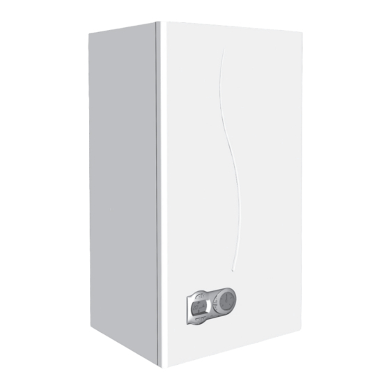
Ferroli DIVAcondens F24 Instructions For Use, Installation And Maintenance
Hide thumbs
Also See for DIVAcondens F24:
Advertisement
DIVAcondens F24/F28
IT - ISTRUZIONE PER L'USO L'INSTALLAZIONE E LA MANUTENZIONE
ES - INSTRUCCIONES DE USO, INSTALACIÓN Y MANTENIMIENTO
EN - INSTRUCTIONS FOR USE, INSTALLATION AND MAINTENANCE
FR - INSTRUCTIONS D'UTILISATION, D'INSTALLATION ET D'ENTRETIEN
RO - INSTRUC IUNI DE UTILIZARE, INSTALARE I ÎNTRETINERE
RU -
,
TR - KULLANMA, KURULUM VE BAK M TALIMATLAR
UA -
,
Advertisement
Table of Contents

Summary of Contents for Ferroli DIVAcondens F24
- Page 1 DIVAcondens F24/F28 IT - ISTRUZIONE PER L’USO L'INSTALLAZIONE E LA MANUTENZIONE ES - INSTRUCCIONES DE USO, INSTALACIÓN Y MANTENIMIENTO EN - INSTRUCTIONS FOR USE, INSTALLATION AND MAINTENANCE FR - INSTRUCTIONS D'UTILISATION, D'INSTALLATION ET D'ENTRETIEN RO - INSTRUC IUNI DE UTILIZARE, INSTALARE I ÎNTRETINERE...
-
Page 2: General Warnings
DIVAcondens F24/F28 Indication during operation Heating 1. GENERAL WARNINGS “d2” Domestic hot water (DHW) “d1“ Comfort Fault “d3” 2.3 Lighting and shutdown Connection to the power supply Switching the boiler off and on On/Off button 2. OPERATING INSTRUCTIONS 2.1 Introduction fig. -
Page 3: Installation
DIVAcondens F24/F28 DHW temperature adjustment 3. INSTALLATION Use the DHW buttons (details 1 and 2 - fig. 1) to adjust the temperature from a min. of 3.1 General Instructions 40°C to a max. of 55°C. BOILER INSTALLATION MUST ONLY BE PERFORMED BY QUALIFIED PERSON-... - Page 4 DIVAcondens F24/F28 Room thermostat (optional) Connection with coaxial pipes IMPORTANT: THE ROOM THERMOSTAT MUST HAVE VOLTAGE-FREE CONTACTS. CONNECTING 230 V TO THE ROOM THERMOSTAT TERMI- NALS WILL PERMANENTLY DAMAGE THE ELECTRONIC BOARD. When connecting time controls or a timer, do not take the power supply for...
- Page 5 Consult the table 6 and identify the losses in meq (equivalent metres) of every com- If the boiler is to be connected DIVAcondens F24/F28 to a collective flue or a single flue ponent, according to the installation position.
-
Page 6: Service And Maintenance
DIVAcondens F24/F28 4. SERVICE AND MAINTENANCE 4.1 Adjustments Gas conversion The unit can work on natural gas or LPG and is factory-set for use with one of these two gases, as clearly shown on the packing and data plate. Whenever a different gas to that... -
Page 7: Troubleshooting
DIVAcondens F24/F28 4.3 Maintenance Fault Faults Possible cause Cure code Periodical inspection To ensure proper operation of the unit over time, have qualified personnel carry out a open yearly inspection, providing for the following checks: Faulty air pressure switch Check the wiring... -
Page 8: Technical Data And Characteristics
DIVAcondens F24/F28 5. TECHNICAL DATA AND CHARACTERISTICS Table. 9 - Key fig. 19, fig. 21, fig. 22 and fig. 23 5 Sealed chamber 37 Cold water inlet filter 7 Gas inlet Ø 1/2” 38 Flow switch 8 Domestic hot water outlet Ø 1/2”... - Page 9 DIVAcondens F24/F28 5.2 General view and main components 5.3 Hydraulic circuit fig. 22 - Heating circuit fig. 21 - General view fig. 23 - DHW circuit...
- Page 10 DIVAcondens F24/F28 5.4 Technical Data Table 5.5 Diagrams Pressure - flow diagrams mbar 9 10 11 12 13 14 15 16 17 18 19 20 21 22 23 24 25 26 27 28 29 A = LPG - B = NATURAL GAS...
- Page 11 DIVAcondens F24/F28...
- Page 12 DIVAcondens F24/F28...
- Page 13 DIVAcondens F24/F28 5.6 Wiring diagram DBM32B 230V 50 Hz 1 2 3 fig. 24 - Wiring diagram Attention: Remove the jumper on the terminal block before connecting the room thermostat or remote timer control. Heating circulating pump C.H. flow temperature sensor...


Need help?
Do you have a question about the DIVAcondens F24 and is the answer not in the manual?
Questions and answers