Advertisement
Quick Links
Advertisement

Summary of Contents for Vent-Axia Solo Pro Series
- Page 1 Solo Pro INTERMITTENT EXTRACT FAN Installation and Wiring Instructions Stock Ref. N° Solo Pro P 409159 Solo Pro T 409160 Solo Pro HTP 409161 Solo Pro TM 409162 220-240V~50Hz IPX4 PLEASE READ INSTRUCTIONS IN CONJUNCTION WITH ILLUSTRATIONS. PLEASE SAVE THESE INSTRUCTIONS.
-
Page 2: Safety And Guidance Notes
Phase) complies with the rating label. D. The Fan should only be used in conjunction with the appropriate Vent-Axia products. E. The fan should only be used in conjunction with fixed wiring. F. When the Fan is used to remove air from a room containing a fuel-burning appliance, ensure that the air replacement is adequate for both the fan and the fuel-burning appliance. -
Page 3: Installation
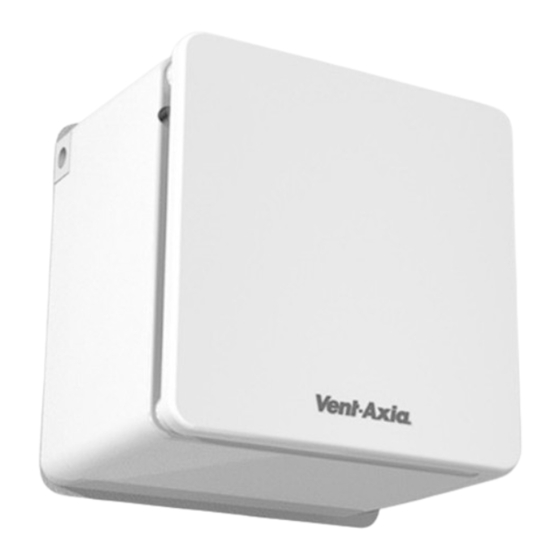
DESCRIPTION The Solo Pro fan is an extract fan for bathrooms and toilets specifically designed for ducted applications. Pullcord, Timer, Humidity and PIR options are available. ACCESSORIES (not supplied) WALL FITTING KIT A range of white (stock ref. 254102) or brown (stock ref. 254100) 100mm wall kits are available for installing into most walls using telescopic liners supplied. - Page 4 B. WIRING. WARNING: THE FAN AND ANCILLARY CONTROL EQUIPMENT MUST BE ISOLATED FROM THE POWER SUPPLY DURING THE INSTALLATION / OR MAINTENANCE. IMPORTANT The cross - sectional area of supply cord used should be ranged from 0.75 -1.5mm The extraction fan is suitable for connection to 220-240V 50Hz supply. ...
-
Page 5: Servicing And Maintenance
IMPORTANT: Upon installation it is possible that the humidity controller will make the fan run continuously until it has acclimatised to the environment. As part of the installation process it is important to set/adjust the humidity sensitivity to the desired position. The controller is already factory set to switch on at about 75% R.H. - Page 6 Fig.3 (Solo Pro TM) Visionex PIR Controller 5 4 3 Please follow the fitting and wiring instructions for the Visionex PIR Controller for full installation instructions. 1 Phase Supply (220-240V 50Hz). FUSE Solo Pro TM Switched Fused Spur Fig.4. Removing the grille for wiring and setting the controls 1) Carefully pull the outer grille away from the fan at each corner.
- Page 7 Fig.4 continued. Remove the PCB cover Push clips together to release the impeller. 5) Remove two screws as shown Fig.5. Wiring and settings Supply cable via side or rear Supply cable connections Secure Supply cable with Cable Clamp Adjust Timer overrun or Humidistat set point (model dependant) as shown.
-
Page 8: Product Fiche
PRODUCT FICHE For Residential Ventilation Units (Complying Commission Delegated Regulation (EU) No 1254/2014) Name: Vent‐Axia Vent‐Axia Vent‐Axia Vent‐Axia Solo Pro P ‐ Solo Pro T ‐ Solo Pro HTP ‐ Solo Pro TM ‐ Model ID (Stock Ref.) : 409159 409160 409161 409162 SEC Class F F E E SEC Value ('Average') 13.97 15.72 26.23 26.23 SEC Value ('Warm') 6.32 7.11 11.86 ... - Page 12 Vent-Axia guarantees its products for two years from date of purchase against faulty material or workmanship. In the event of any part being found to be defective, the product will be repaired, or at the Company’s option replaced, without charge, provided that the product:- ...


Need help?
Do you have a question about the Solo Pro Series and is the answer not in the manual?
Questions and answers