Siemens SIPLUS CMS4000 Operating Instructions Manual
Hide thumbs
Also See for SIPLUS CMS4000:
- Operating instructions manual (39 pages) ,
- Operating instructions manual (32 pages) ,
- Operating instructions manual (36 pages)

Related Manuals for Siemens SIPLUS CMS4000


Summary of Contents for Siemens SIPLUS CMS4000
-
Page 1: Table Of Contents
Operating Instructions SIPLUS CMS4000 Wiring Preface Product overview SIPLUS CMS4000 Typical configurations Cable Cable types 6AT8000-2AB… Connecting cable Appendix Operating Instructions - English Version 2017-06 SIPLUS CMS4000 Cable Operating Instructions, 06/2017, A5E02298098B-01... - Page 2 Siemens. Trademarks All designations marked with ® are registered trademarks of Siemens AG. Other designations in this documentation might be trade- marks which, if used by third parties for their purposes, might infringe upon the rights of the proprietors.
- Page 3 Operating Instructions SIPLUS CMS4000 Wiring Table of Contents Preface..........................4 Purpose of this document ..................4 Required basic knowledge ..................4 Validity of this document ..................4 Modification compared with the previous version ............4 CE marking ......................4 Standards ......................4 Position in information environment ................4 Directory ........................5...
-
Page 4: Preface
Position in information environment In addition to this operating instructions you need the manual of the applied ION and IFN hardware. SIPLUS CMS4000 IFN AI, IFN VIB-A, ION PROFIBUS DP Spy T001, MCN11 and RPN IEEE1394. SIPLUS CMS4000 Cable Operating Instructions, 06/2017, A5E02298098B-01... -
Page 5: Directory
Operating Instructions SIPLUS CMS4000 Wiring Directory This operating instructions consist of chapters for guidance and of technical data. They contain the following topics: · Product overview (Chapter 2) · Typical configurations (Chapter 3) · Cable types (Chapter 4) · Connecting the cable (Chapter 5) ·... -
Page 6: Product Overview
Operating Instructions SIPLUS CMS4000 Wiring Product Overview What is SIPLUS CMS? SIPLUS CMS is an industrial-suited Condition Monitoring System for technical and tech- nological services in industrial plants. SIPLUS CMS is a modular, scalable analysis and diagnosis system. It is optimized for reaction less measurement of analog, binary and numerical data. -
Page 7: What Is An Interface Node Ion Or Ifn
Operating Instructions SIPLUS CMS4000 Wiring What is an Interface Node ION or IFN? Definition With an ION or IFN binary, analog or vibration signals are measured and transfered via bus system to an industry PC according to the EEE1394a Standard. - Page 8 Operating Instructions SIPLUS CMS4000 Wiring Picture 3 Front view MCN11 SIPLUS CMS4000 Cable Operating Instructions, 06/2017, A5E02298098B-01...
-
Page 9: Typical Configurations
Operating Instructions SIPLUS CMS4000 Wiring Typical Configurations Tree topology The IEEE1394a technology allows to create extended networks with up to 63 partici- pants. The attendance of one branch must not be more than 16 devices. The tree-topology allows the construction of a network system by connecting one bus participant with two further ones. -
Page 10: Connection With Fibre Optic Cable
Operating Instructions SIPLUS CMS4000 Wiring Interface Node (IFN) IFN/IFN-Cable IFN/IFN-Cable Picture 5 Line topology with IFN Connection with fibre optic cable The MCN11 can be connected to any IEEE1394 – connection (LNK0/1/2) on the IFN. In accordance to the minimum distance up to three MCN11 can operate at the same time. - Page 11 Operating Instructions SIPLUS CMS4000 Wiring PC / SIPLUS CMS Microbox Multi-Port-Repeater (RPN IEEE1394B T001/T002) RPN/PC-Cable Media Converter Node (MCN11) Interface Node (IFN) IFN/MCN-Cable Picture 7 Optical connection of a PC on a CMS4000 System SIPLUS CMS4000 Cable Operating Instructions, 06/2017, A5E02298098B-01...
-
Page 12: Cable Types
Operating Instructions SIPLUS CMS4000 Wiring Cable Types Overview The following chart gives a survey about all cables and their usage combined with ION, IFN, MCN und RPN: Name Chapter Identifier CABLE-IEEE1394A-66/46 2AA00 CABLE-IEEE1394A-8F 2AB20-1 CABLE-IEEE1394A-8M 2AB20-2 CABLE-Power 2AB30 IFN ADD... -
Page 13: Cable-Ieee1394A-66/46
Operating Instructions SIPLUS CMS4000 Wiring CABLE-IEEE1394A-66/46 Name: CABLE-IEEE1394A-66/46 Application: IEEE1394 coupling cable PC-ION, PC-RPN, ION-ION, ION-RPN Length: 30cm, 100cm, 200cm, 450cm Order numbers: CABLE-IEEE1394A-66-0030 (30 cm) 6AT8000-2AA00-1AA3 CABLE-IEEE1394A-66-0100 (100 cm) 6AT8000-2AA00-1AB0 CABLE-IEEE1394A-66-0200 (200 cm) 6AT8000-2AA00-1AC0 CABLE-IEEE1394A-66-0450 (450 cm) 6AT8000-2AA00-1AE5 CABLE-IEEE1394A-46-0450 (450 cm) -
Page 14: Cable-Ieee1394A-8F
Operating Instructions SIPLUS CMS4000 Wiring CABLE-IEEE1394A-8F Name: CABLE-IEEE1394A-8F Application: IEEE1394 coupling cable PC-IFN, ION-IFN, RPN-IFN Length: 40cm, 200cm, 450cm Order numbers: CABLE-IEEE1394A-8F-0040 (40 cm) 6AT8000-2AB20-1AB0 CABLE-IEEE1394A-8F-0200 (200 cm) 6AT8000-2AB20-1AC0 CABLE-IEEE1394A-8F-0450 (450 cm) 6AT8000-2AB20-1AE5 Picture 10 CABLE-IEEE1394A-8F This cable is used for IEEE1394 coupling of PC-IFN, ION-IFN and RPN-IFN. -
Page 15: Cable-Power
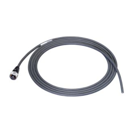
Operating Instructions SIPLUS CMS4000 Wiring CABLE-Power Name: CABLE-Power Application: Power cable Length: 135cm, 200cm, 500cm, 1000cm Order numbers: CABLE-Power-135-0000 (135 cm) 6AT8000-2AB30-1AA1 CABLE-Power-200-0000 (200 cm) 6AT8000-2AB30-1AA2 CABLE-Power-500-0000 (500 cm) 6AT8000-2AB30-1AA5 CABLE-Power-1000-0000 (1000 cm) 6AT8000-2AB30-1AB0 Picture 12 CABLE-Power This cable is used for energy supply of the IFN. To forward the power from the first IFN to the following ones in a line topology IFN ADD must be applied, see. -
Page 16: Ifn Add
Operating Instructions SIPLUS CMS4000 Wiring Chart 1: Pin assignment PWR Assignment Wire color View M24 (ground) brown +24 V DC (18…32 V DC) white blue (power down, ext. restart) free black free grey or green/yellow IFN ADD A cable set consists of one power cable with Y-plug for straight power forwarding to a neighbour IFN and one IEEE1394A coupling cable. - Page 17 Operating Instructions SIPLUS CMS4000 Wiring Warning The IFN ADD power cable with Y-plug is designed for max. current load of 4 A . Maximum 16 IFNs are allowed to be connected in a line. Notice CABLE-Power-xxx-0000 (6AT8000-2AB30-1Axx) and CABLE-IEEE1394A-88-0020 (6AT8000- 2AB20-2AD2) must be applied to obtain protection class IP67.
-
Page 18: Cable-Io
Operating Instructions SIPLUS CMS4000 Wiring CABLE-IO Name: CABLE-IO Application: Input/Output-cable IFN-sensor Length:: 200cm, 500cm, 1000cm Order numbers: CABLE-IO-200-0000 (200 cm) 6AT8000-2AB40-1AA2 CABLE-IO-500-0000 (500 cm) 6AT8000-2AB40-1AA5 CABLE-IO-1000-0000 (1000 cm) 6AT8000-2AB40-1AB0 Picture 16 CABLE-IO This cable allows connecting the sensor technology to the IFN. The cable can be used for IFNA AI and IFN VIB-A. - Page 19 Operating Instructions SIPLUS CMS4000 Wiring The following chart shows the assignment of the IEPE inputs (CH1 - CH6) using an IFN VIB-A. Chart 4 Pin assignment IEPE sensor input (CH1-CH6) Assignment Wire color View GND (ground) brown free white signal...
-
Page 20: Accessories
Operating Instructions SIPLUS CMS4000 Wiring Accessories Mounting brackets for wall mounting are available for IFN - IFN Mounting Set (6AT8000- 2BB00-0XB0) and for MCN11 - MCN Mounting Set (MLFB 6AT8000-2BB00-0XC0). Unused jacks can be closed by a capping set, IFN Coping Set (MLFB 6AT8000-2BB00- 0XA0). -
Page 21: Connecting Cable
Operating Instructions SIPLUS CMS4000 Wiring Connecting Cable Connect M12-plug Caution The following pictures (picture 17, picture 18 , picture 19) shall explain the principle of connecting the cable and may contain deviations from the used plug types. 1. Push the M12 connector vertical in the respective flange sleeve, so that connector slot and the knurled ring nut lie on top of each other. - Page 22 Operating Instructions SIPLUS CMS4000 Wiring Picture 19 lock the plug 3. The end position (interlock) of the M12-socket plug is finished now. Picture 20 correctly plugged in Caution Avoid canting between M12 connector and socket plug! Only when the installation is correct, the protection category IP67 and safe contacting is guaranteed.
-
Page 23: Fibre Optic Cable Connection
Operating Instructions SIPLUS CMS4000 Wiring Fibre optic cable connection 5.2.1 MCN11 fibre optic cable (LWL) 1. Open the 4 screws on the device with an Allen key (SW3). Picture 21 Open all 4 screws 2. Release only the screwcap of the screw connection (PG-screwing) and pull the „SC/PC plug“... - Page 24 Operating Instructions SIPLUS CMS4000 Wiring 4. Insert the SC/PC-plug of the LWL cable strands through the cable entry into the housing. Case screw (4x) Sealing insert Screwcap SC/PC-plug Cable entry Picture 23 LWL-cable entry configuration 5. Connecting „SC/PC-plugs“. Device 1 Device 2 ▼▲...
- Page 25 Operating Instructions SIPLUS CMS4000 Wiring 6. Slide the sealing insert flush in the cable entry so that the LWL-single connector lays parallel in the box (in order to avoid a mechanical overload of LWL). 7. Screw the retainer nut tightly onto the cable entry. The recommended torsional mo- ment is 10Nm.
-
Page 26: Rpn Ieee1394A Fibre Optic Cable (Lwl)
Operating Instructions SIPLUS CMS4000 Wiring 5.2.2 RPN IEEE1394A fibre optic cable (LWL) According to its design the RPN has one or two duplex SC/PC62.5 fibre optic cable adapter. LWL adapter ground IEEE1394 adapter (LNK) LWL adapter power supply Picture 26 RPN IEEE1394B T002 Interface... -
Page 27: Appendix
Operating Instructions SIPLUS CMS4000 Wiring Appendix Service & Support in the Internet In addition to our documentation pool we offer our complete knowledge basics on the In- ternet: www.siemens.com/automation/service&support There you find: • The newsletter, which is constantly updated to provide you with the latest information about your products.
Need help?
Do you have a question about the SIPLUS CMS4000 and is the answer not in the manual?
Questions and answers