Advertisement
Quick Links
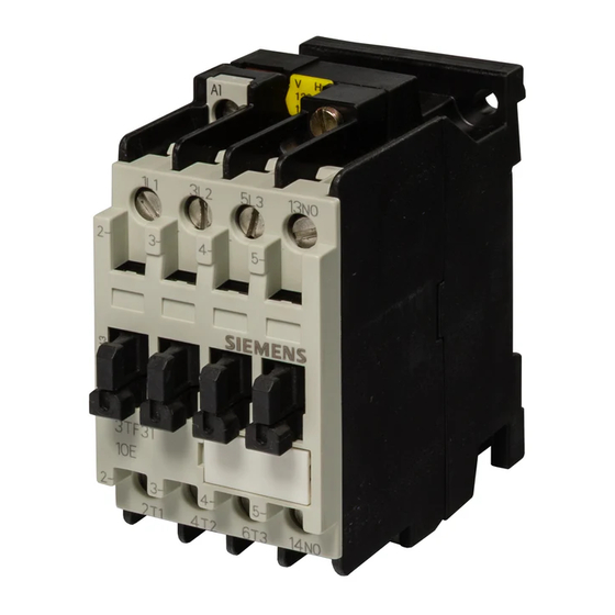
Contactor
Instructions
Limited protection against contact with live parts
!
Degree of protection IP 20 to IEC 60529
Safe from finger touch to DIN VDE 0106, Part 100
Commissioning and maintenance by qualified personnel only.
Follow the operating instructions.
WARNING:
HAZARDOUS VOLTAGE
CAN CAUSE ELECTRICAL SHOCK
DISCONNECT POWER BEFORE PROCEEDING
WITH ANY WORK ON THIS EQUIPMENT.
Installation
For dimension drawings (dimensions in mm) see
> Fig. I a
a.c. operated
> Fig. I b
d.c. operated
1)
Minimum clearances from earthed parts
Snap onto 35 mm standard mounting rail to DIN EN 50 022 or fix on a
plain surface with two M4 screws. With screw mounting, always use
plain washers and spring washers.
Cover the contactors during installation if foreign particles, such as
swarf, can fall onto them. Install contactors in a housing if they are
exposed to dirt, dust or aggressive atmospheres.
For permissible mounting positions see
> Fig. II a
a.c. operated
> Fig. II b
d.c. operated
Connection
The terminal screws can be tightened with a power screwdriver.
Screwdriver blade width: 5 to 6 mm
Permissible cross>sections for main and auxiliary conductors :
Solid
Finely stranded, with end sleeve
AWG wires
Tightening torque standard type
Tightening torque auxiliary contact block
Use 75 ∞C copper wire only.
For circuit diagram and position of connection terminals see Fig. III.
For circuit diagram (NEMA) see Fig. A.
> Fig. III a
1NO
> Fig. III b
1NC
> Fig. III c
without auxiliary contacts
Operation
Observe operating voltage (see rating plate of magnet coil).
The operating state of the contactor is shown by the position of the
contact carrier; see Fig. IV.
When the system voltage is applied and the load is connected,
!
do not operate the contactor by pressing down the contact
carrier.
Maintenance
The following components can be replaced: magnet coil and single>
pole auxiliary contact block 3TX40.
For Order Nos. see Catalog NSK.
Only use of original spare parts ensures the operational safety of the
contactors.
2
AND BURNS.
2
2¥0.5 to 1 mm
2
2¥1 to 2.5 mm
2
1¥4 mm
2
2¥0.75 to 2.5 mm
2¥AWG 18 to 12
0.8to 1.4 Nm/7 to 12 lb
0.8to 1.1 Nm/7 to 10 lb
Order No.: 3ZX1012>0TF00>1AA2
Cleaning
Remove dust by suction.
Auxiliary contact block
For replacement see Fig. V.
Magnet coil
For coil replacement see Fig. VI.
> Fig. VI a
a.c. coil
> Fig. VI b
d.c. coil
Ensure that the pole faces of the magnet coil are clean. Do not use grease
solvents or sharp objects for cleaning.
Technical Data
Permissible ambient temperature
> Operation
> Storage
Main circuit
Rated insulation voltage U i
Rated operational current I e /AC>1 (55 ∞C)
> Open model
> Closed model
Rated operational voltage
> 230 V
> 400 V
> 500 V
> 690 V
Horsepower Ratings (
Rated insulation voltage U
Continuous current
(open and enclosed type)
.
in
> 200 V
.
> 230 V
in
> 460 V
> 575 V
Suitable for use on a circuit capable of delivering not more than 5000 rms
symmetrical amperes, 600 V max.
Short>circuit protection:
Degree of protection to
DIN VDE 0660 part 102 A/IEC 60947>4 **
> Assignment type 1
> Assignment type 2
> Non>welding I K f100¥I e
> Circuit>breaker, C>char.
3TF30, 3TF31
DIN VDE 0660, IEC 60947
> 25 to+55 ∞C
> 50 to+80 ∞C
AC 690 V
A
20
A
16
Motor rating P
3TF30
kW
2.4
kW
4
kW
5.5
kW
5.5
and
ratings)
AC 600 V
i
Rated output of three>phase
motors at 60 Hz
3TF30..>....1
NEMA/EEMAC
SIZE 00
A
9
hp
1Ω
hp
1Ω
hp
2
hp
2
Fuse>links Duty class gL
(gG)
3TF30
A
35
A
16
A
10
A
16
/AC>3
N
3TF31
3.3
5.5
7.5
7.5
3TF30 3TF31
20
20
2
3
3
3
5
7.5
7.5
10
3TF31
35
16
10
25
Advertisement

Related Manuals for Siemens 3TF30


Summary of Contents for Siemens 3TF30
- Page 1 Contactor 3TF30, 3TF31 DIN VDE 0660, IEC 60947 Instructions Order No.: 3ZX1012>0TF00>1AA2 Limited protection against contact with live parts Cleaning Degree of protection IP 20 to IEC 60529 Remove dust by suction. Safe from finger touch to DIN VDE 0106, Part 100 Commissioning and maintenance by qualified personnel only.
- Page 2 Auxiliary circuit Fig. A Rated operational Rated operational voltage current I e /AC>15/AC>11 > 230 V CIRCUIT > 240 V PROTECTIVE > 400 V DEVICE PHASE > 415 V MOTOR > 500 V (IF USED) > 690 V FUSE FUSE Rated operational Rated operational voltage PRI.
Need help?
Do you have a question about the 3TF30 and is the answer not in the manual?
Questions and answers